Hardware Installation
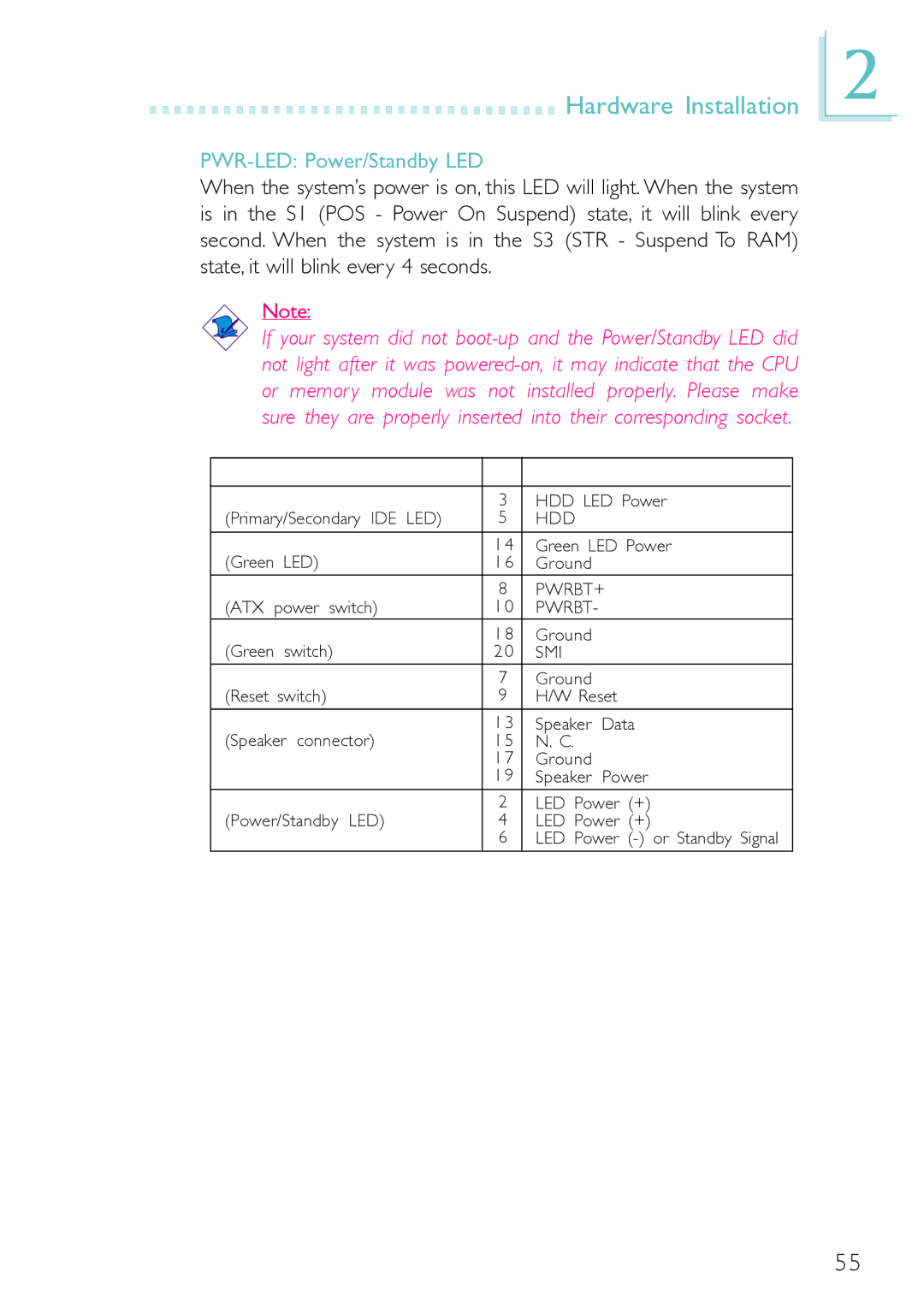
PWR-LED: Power/Standby LED
When the system’s power is on, this LED will light. When the system is in the S1 (POS - Power On Suspend) state, it will blink every second. When the system is in the S3 (STR - Suspend To RAM) state, it will blink every 4 seconds.
Note:
If your system did not
|
| Pin | Pin Assignment | |
3 | HDD LED Power | |||
(Primary/Secondary IDE LED) | 5 | HDD |
| |
|
|
|
| |
| 1 4 | Green LED Power | ||
(Green LED) | 1 6 | Ground |
| |
8 | PWRBT+ | |||
(ATX power switch) | 1 0 | PWRBT- |
| |
| 1 8 | Ground |
| |
(Green | switch) | 2 0 | SMI |
|
RESET |
| 7 | Ground |
|
(Reset | switch) | 9 | H/W Reset | |
SPEAKER | 1 3 | Speaker | Data | |
(Speaker connector) | 1 5 | N. C. |
| |
|
| 1 7 | Ground |
|
|
| 1 9 | Speaker | Power |
2 | LED Power (+) | |||
(Power/Standby LED) | 4 | LED Power (+) | ||
|
| 6 | LED Power | |
2
55