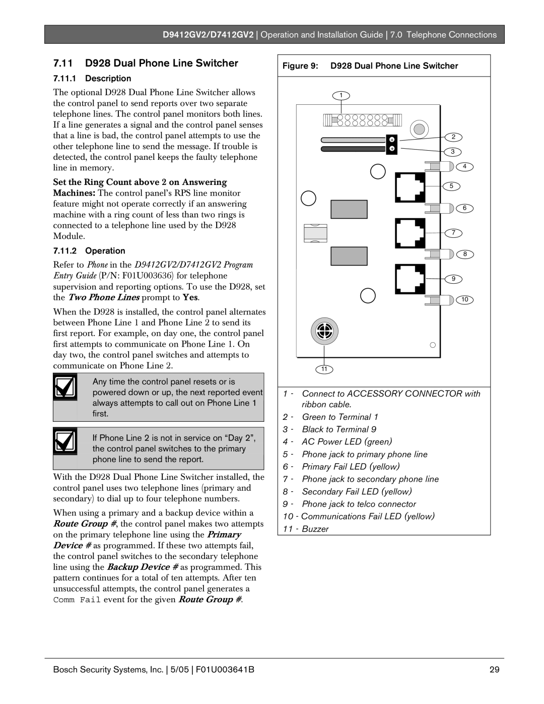
D9412GV2 specifications
The Bosch D9412GV2 is an exceptional dishwasher that stands out in the competitive world of home appliances. Known for its reliability and advanced features, this model offers a blend of cutting-edge technology and user-friendly design that appeals to modern households.One of the most noteworthy features of the D9412GV2 is its impressive cleaning performance. Boasting a unique combination of powerful jets and specialized wash cycles, it ensures that even the toughest stains are removed effectively. The dishwasher features Bosch’s patented PrecisionWash system, which utilizes intelligent sensors to monitor the wash cycle’s progress and adjust the water spray for optimal cleaning results. This not only guarantees sparkling dishes but also conserves water and energy.
In terms of capacity, the D9412GV2 does not disappoint. It has a spacious interior that is designed to accommodate up to 16 place settings, making it an ideal choice for families or those who frequently entertain guests. The adjustable racks and flexible loading options allow users to maximize space and customize the dishwasher to suit their unique needs. The third rack is particularly useful for utensils and smaller items, providing additional space that enhances efficiency.
The dishwasher is also engineered with noise reduction features for a quieter operation. With a sound rating of 44 decibels, it operates silently in the background, allowing for uninterrupted conversations and a peaceful home environment. This is especially beneficial for open-concept living spaces.
Energy efficiency is another hallmark of the Bosch D9412GV2. It is Energy Star certified, reflecting its commitment to sustainable practices. It uses less water and electricity without compromising performance, making it a responsible choice for eco-conscious consumers.
Moreover, the presence of the Home Connect feature allows users to control and monitor their dishwasher remotely via a smartphone app. This innovative technology enables users to start or stop cycles, receive notifications, and even download new wash programs, adding convenience and flexibility to busy lifestyles.
In conclusion, the Bosch D9412GV2 is a state-of-the-art dishwasher that excels in cleaning performance, capacity, and energy efficiency. With its innovative technologies and thoughtful design, it represents Bosch's commitment to quality and customer satisfaction, making it a valuable addition to any kitchen.

