Connection en 23 | |
|
|
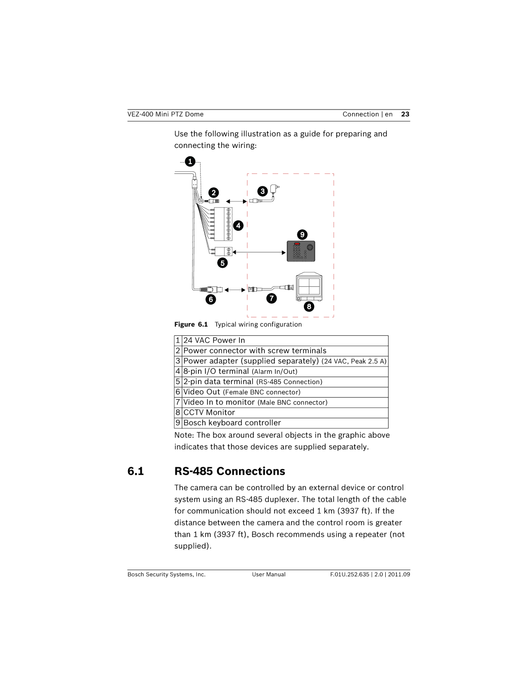
Use the following illustration as a guide for preparing and connecting the wiring:
Figure 6.1 Typical wiring configuration
1 | 24 VAC Power In |
2 | Power connector with screw terminals |
3Power adapter (supplied separately) (24 VAC, Peak 2.5 A)
4
5
6Video Out (Female BNC connector)
7Video In to monitor (Male BNC connector)
8 | CCTV Monitor |
9 | Bosch keyboard controller |
Note: The box around several objects in the graphic above indicates that those devices are supplied separately.
6.1RS-485 Connections
The camera can be controlled by an external device or control system using an
Bosch Security Systems, Inc. | User Manual | F.01U.252.635 2.0 2011.09 |