Assembly Guide
Step 9: SECURING THE CONSOLE/
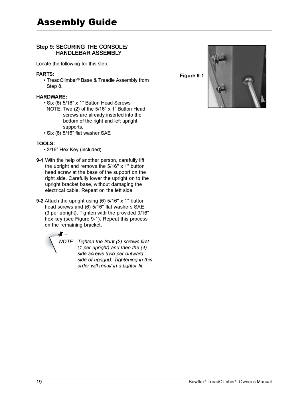
HANDLEBAR ASSEMBLY |
|
Locate the following for this step: |
|
PARTS: | Figure |
• TreadClimber® Base & Treadle Assembly from |
|
Step 8. |
|
HARDWARE:
•Six (6) 5/16” x 1” Button Head Screws NOTE: Two (2) of the 5/16” x 1” Button Head
screws are already inserted into the bottom of the right and left upright supports.
•Six (6) 5/16” flat washer SAE
TOOLS:
• 3/16” Hex Key (included)
Note: Tighten the front (2) screws first (1 per upright) and then the (4) side screws (two per outward side of upright). Tightening in this order will result in a tighter fit.
19 | Bowflex® TreadClimber® Owner’s Manual |