Page
Page
Preface
Contents
Chapter III Disassembly and Reassembly III-1
Chapter IV Maintenance and Troubleshooting
Environment-Friendly
High Resolution and Fast Printing Speed
Versatile Paper Handling
Enhanced Memory Management
Popular Printer Emulation Support for HL-1040/1050 only
USB Interface for HL-1050 only
Optional Apple Macintosh Interface for HL-1040/1050 only
CPU
Printing
Functions
Electrical and Mechanical
820W or less
Paper Loading
Print Delivery
Paper
Effective Printing Area Printable area
Monarch
228.6mm 304.8mm 203.2mm 296.3mm 12.7mm 12.0 11.66 Dots
Manufacturedk
Laser Safety 110 120V Model only
FDA Regulations 110 120V Model only
Valid
General Block Diagram HL-820/1020
Chapter II Theory of Operation
Shows a general block diagram of the HL-1040 printer
HL-1040
Shows a general block diagram of the HL-1050 printer
HL-1050
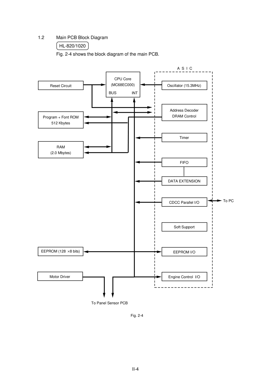
Main PCB Block Diagram HL-820/1020
Shows the block diagram of the main PCB
II-5
II-6
Main PCB CPU Core HL-820/1020/1040
HL-1050
Asic HL-820/1020/1040
NMI
Fifo
Scanint Cdcc / Boise / Data Extension
Eeprom I/O
Page
USB
Cdcc
One output port and one I/O port are assigned II-13
Page
3 ROM HL-820/1020/1040
Dram HL-820/1020/1040
Optional RAM HL-1050
Optional Serial I/O HL-1040/1050
Eeprom HL-820/1020/1040
Reset Circuit HL-820/1020/1040
Cdcc I/O HL-820/1020/1040
22 shows the Cdcc interface circuit II-20
Engine I/O HL-820/1020/1040
23 shows the engine interface circuit II-21
24 shows the engine interface circuit II-22
Paper Feed Motor Drive Circuit HL-820/1020/1040
Power Supply Low-voltage Power Supply
Panel Sensor PCB
High-voltage Power Supply
GND Paper Sensor
Mechanics
Overview of Printing Mechanism
Paper Transfer Paper Supply
Paper Registration
Paper Eject
Sensors Cover Sensor
Toner Empty Sensor
Cleaner Roller
Drum Unit Photosensitive Drum
Primary Charger
Development Roller
Exposure Stage
Developing
Transfer
Fixing Stage
Drum Cleaning Stage
Erasing Stage
III-1
TAPTITE, CUP S
Screw
III-2
Bottom
III-3
Output Tray Assy
Drum Unit
III-4
Top Cover
Rear Cover
MP Sheet Feeder Assy
III-5
Fixing Unit
III-6
III-7
Scanner Unit
III-8
III-9
Main PCB Assy
Base Plate Assy
Panel Sensor PCB Assy
Low-voltage Power Supply PCB Assy
High-voltage Power Supply PCB Assy
Sub Fan Motor Assy
Main Fan Motor Assy
Drive Unit
Main Motor Assy
Sub Motor Assy
Extension Support Wire
Paper Support
Packing
Chapter IV Maintenance and Troubleshooting
Initial Check
Basic Procedure
Periodical Replacement Parts
Toner Cartridge
Image Defects
Image Defect Examples
Troubleshooting Image Defects
Light
Dark
PCB
Completely blank
All black
Dirt on the back of paper
Black and blurred vertical streaks
Black and blurred horizontal stripes
White vertical streaks
Faulty registration
Black vertical streaks in a gray background
Poor fixing
Image distortion
Faint print
White spots
Black spots
Black band
Gray background
Hollow print
Downward fogging of solid black
Horizontal lines
Light rain
Ghost
Location of High-voltage Contacts and Grounding Contacts
Location of Feed Roller Shaft and Grounding Contacts
Paper JAM
No AC power supplied
No DC power supplied
Main motor unrotated
No paper supplied
BD failure
Insufficient output from high-voltage power supply unit
Fixing heater temperature failure
Scanner failure
Double feeding
Wrinkles
Incorporated Inspection Modes
Lamp Type of inspection
Page
Fuser Malfunction
Service a Service B CPU Runtime Error
Error Codes
3 0 0 0 0 a N B
Appendix 2. Connection Diagram, HL-820/1020
Appendix 3. Connection Diagram, HL-1040
Appendix 4. Connection Diagram, HL-1050
Code
Appendix 6. Main PCB Circuit Diagram, HL-820/1020/1040, 2/2
Appendix 7. Main PCB Circuit Diagram, HL-1050, 1/5
Appendix 8. Main PCB Circuit Diagram, HL-1050, 2/5
Appendix 9. Main PCB Circuit Diagram, HL-1050, 3/5
Appendix 10. Main PCB Circuit Diagram, HL-1050, 4/5
Appendix 11. Main PCB Circuit Diagram, HL-1050, 5/5
Appendix 12. Panel Sensor PCB Circuit Diagram
Low-voltage
PS Circuit
220
C17 D13 D12 C22 R18
C11 R10
Power Supply PCB Circuit Diagram
Appendix 18. HOW to Know Drum Unit Life & page Counter
Print Test Print or Print Configuration
How to Read the Drum Life
How to Read the Page Counter
Appendix 19. Diameter / Circumference of Rollers
Parts Reference List
REF.NO Code ’TY Description Symbol Remark
B48K056 201A
Contents
11-1 11-2 11-5 11-4
3. Main PCB HL-1040 OTHERS/ISRAEL
5. Main PCB HL-1050 OTHERS/ISRAEL
Power Cords & Packing Drawing
12-2 12-3 12-4 12-1
Drive Unit
MP Sheet Feeder
Covers
Main PCB ASSY, HL-820 SP
MROM1050-EVEN
Panel Sensor PCB
High Voltage Power Supply
Accessories
Packing Materials
Model LT-24CL
REF.NO Code ’TY Description Remark
Contents
Lower Tray Unit REF.NO. Code QTY Description Remark
Model
Feb., 1999 54S004BE0
Page
Preface
Product Outline
Regulations
IEC 825 Specification for 220-240 V Model only
For Finland and Sweden
Safety Alert Symbol
Introductory Information
Hazardous Voltage
Hazardous Powder
Label Location
Hot Caution Label Laser Caution Label
Product Outline
Specifications
Environmental conditions
Basic layout of printer set-up location
Unpacking
Installation Procedures
Install the printer onto the lower tray unit
Check the three alignment guide pins on the lower tray unit
Remove the set-up guides R/L from the unit
Connect the LT signal connector into the printer
Install the covers
Relocating the printer / Test print
Maintenance
Disassembly
Paper Sensor PEL / OHP Sensor Ohpl
Paper Feeding Roller / Separation Pad
Clearing Paper Jams
PR98235
REF.NO Code QTY Description Remark
PR Driver Disk ASSY1, 820 Windows
PR Driver Disk ASSY1, 1020 Windows
PR Driver Disk ASSY1, 1040 Windows
24 UL8516001 1 Extension Support Wire
EL PCB Unit
Rubber Foot Chng
17 UL8508001 1 Insulation Sheet
Base Plate
16 UL8508001 1 Insulation Sheet
Mylar LABEL, MFC-P2000 Canada
Mini Clamp
Code Qtydescription Symbol Remark
Fixing Units
REF.NO Code Qtydescription Remark
Fixing Unit Y, 120V SP
REF.NO Code QTY Description Symbol Remark
UH3419001 1 Heat Roller YS Assy SP
Main PCB Assy
Conductive Tape
Cleaner
Cleaner Legend
MP Sheet Feeder Assy SP
Fixing UNIT, 120V SP
CLEANER, LEG
Fixing UNIT, LEG 230V SP
Heat ROLLER, LEG SP
Main PCB ASSY, US SP
CARTON, EUR HL-820
CARTON, can HL-1020
CARTON, USA HL-1040
CARTON, can HL-1040
PR99057
Base Plate
Quick Setup Guide
For USA & Canada Only
If you have comments or suggestions, please write us at
Table of Contents
Action 1 Check the Supplied Items
Power Supply
Environment
Action 3 Install the Toner Cartridge/Drum Unit
Action 4 Load Paper into Your Printer
Paper Type Paper Size
Secure the connection with the wire clips. ②
Select Search for the best driver for your device
Select CD-ROM drive
Set the printer port to USB
Troubleshooting
Action 6 Plug in and Turn on Your Printer
Printing a Test Sample
For Windows 95/98/NT
For Windows 3.1/3.11
Page
Action 7-3 Prepare Windows 3.1 for the Printer
HL-1040 HP LaserJet IIP
Installing the Remote Printer Console
What Does Remote Printer Console Do?
Using the Remote Printer Console Main Program
Using the Printer Status Monitor Program
Action 7-5 Prepare Macintosh for the Printer
Only for HL-1040/1050 Users
Data Toner Lamp
Lamps and Switch
Ready Paper Lamp
Drum Lamp
Alarm Lamp
Switch
Other Control Features
Sleep Mode
Replacing the Toner Cartridge
High Temperature
Page
Replacing the Drum Unit
Do not remove the starter sheet
Page
Alarm Indications AT a Glance
Operator Calls
For HL-1040/1050
Drum Alarm Ready
Service Calls
Drum Alarm Ready Data
Additional Memory HL-1050 Only
Installing the Simm
Printer Specifications
Printing
Functions
Electrical and Mechanical
Regulations
Geräuschemission / Acoustic Noise Emission For Germany Only
Important For Your Safety
Important Wiring Information For U.K. only
Void the Warranty
Page
Please read this manual thoroughly before using the printer
HL-800/1000 Series
Table of Contents
Index
Definitions of Warnings, Cautions, and Notes
To Use the Printer Safely
Shipment of the Printer
BBS
Internet Address
Finding Out How to Use the Printer
About the Guidebooks
About Your Printer
Printer Overview
Features
High Resolution and Fast Printing Speed HL-820
For HL-1040/1050 Only Remote Printer Console Program for DOS
For HL-1040/1050 Only Popular Printer Emulation Support
For HL-1050 Only USB Interface
Enhanced Memory Management
Environment-Friendly Economy Printing Mode
Low Running Cost
Operating and Storage Environment
Page
Paper Specifications
Labels / Transparencies
Remarks
Cut Sheet
Special Paper
Fan the Paper Straighten the Paper
Envelopes
Envelopes
MULTI-PURPOSE Sheet Feeder
Loading Paper into the Feeder
Opening the Feeder Loading Paper or Envelopes in the Feeder
Moving the Paper Guide Closing the Feeder
Two Side Printing Manual Duplexing
Manual Feed Slot
When you load one sheet of paper manually
When you load more than one sheet of paper manually
USER’S Guide
Output Tray and Paper Support Wire
Opening the Output Tray Extending the Extension Support Wire
Chapter Control Panel
Data Toner Lamp
Cancel printing
Error Recovery
Sleep Mode
Wake-up
Drum
Test Print Mode
Lamp Lit Choice Function
Only
Selecting the RS-422A Apple or RS-232C IBM Serial Interface
Setting the Serial Interface Parameters
Selecting the RS-422A Apple or RS-232C IBM Serial Interface
Bits
Bit
DTR only
Off
LocalTalk
Connecting the Serial Interface Cable
None
Options
Minimum Memory Recommendation including resident memory
Installing the Simm
Removing the Main Controller Board
Options
Chapter Maintenance
Removing the Drum Unit
Turning the Lever to Close the Shutter
Removing the Old Toner Cartridge
Turn the drum unit upside down gently
Cleaning the Primary Corona Wire
11 Drum Unit Nearly at the End of its Life
12 Removing the Drum Unit
Do not remove the starter sheet
14 Removing the Toner Cartridge
17 Installing the Drum Unit
Cleaning the Printer
Cleaning the Printer Exterior
Cleaning the Printer Interior and Drum Unit
20 Turning off the Switch and Unplugging
Gently wipe the scanner window with a soft dry cloth
See the section Replacing the Drum Unit in Chapter
24 Removing the Drum Unit Assembly
RE-PACKING the Printer
25 Placing the Drum Unit in the Plastic Bag
Toner ↔
Alarm ↔
Paper ↔
For HL-1050 only
If the error occurs again, the interface hardware may be
Service Call RAM error Service a Service B
Paper Jams
Locating Paper Jam Position
Paper Jam in the Multi-Purpose Sheet Feeder
Do Not Pull the Jammed Paper from the Output Tray
Paper Jam near the Drum Unit or at the Paper Output Tray
Paper Jam in the Fuser Unit
Power switch is on
Setting Up the Printer Hardware
Setting Up the Printer for Windows
For HL-1050
Setting Up the Printer for DOS For HL-1040/1050 Only
Paper Handling
Printing
Printer cannot print full pages of a document. a
Print Quality
Together right now, over
Toner scatters and stains the printed
Printer Interior and Drum Unit
Chapter Appendix
Functions
Electrical and Mechanical
Parallel Interface Specifications
Fig. A-1 Parallel Interface Cable
Universal Serial BUS USB Interface HL-1050 only
Resident Fonts
HL-1040 Bitmapped Fonts
HL-1050 Bitmapped Fonts
Scalable Fonts
Intellifont Compatible Fonts
Symbol SETS/CHARACTER Sets
OCR Symbol Sets HL-1050 Only
HP LaserJet IIP Mode HL-1040
HP LaserJet 6P Mode HL-1050
Epson Mode HL-1040/1050
IBM Mode HL-1040/1050
HP LaserJet IIP / HP LaserJet 6P
HP LaserJet IIP/6P, Epson FX-850, IBM Propritner XL
Appendix
Trademarks
Compilation and Publication Notice
Industry Canada Compliance Statement For Canada Only
International Energy Star Compliance Statement
FDA Regulations For 110-120 V Model Only
Laser Safety For 110-120 V Model Only
Radio Interference 220-240 V Model Only
IEC 825 Specification For 220-240 V Model Only
EMC
Lpa 70 dB a DIN 45635-19-01-KL2
Important Wiring Information For U.K. only
Index
3-3