IP ROUTING NETWORK WITH PPP DEVICES
Configure SITE1
Next, select the RIP Propagation Control. This controls how a static route is propagated via RIP. Press 3 to propagate only when the Next Hop is connected. This flag indicates that the route information is propagated via RIP only when the next hop router is connected to SITE1.
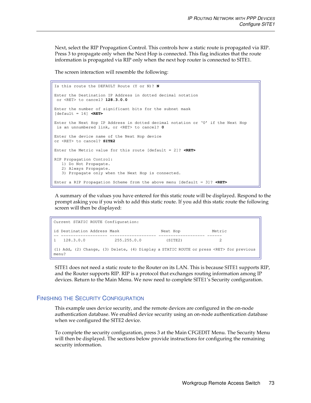
The screen interaction will resemble the following:
Is this route the DEFAULT Route (Y or N)? N
Enter the Destination IP Address in dotted decimal notation or <RET> to cancel? 128.3.0.0
Enter the number of significant bits for the subnet mask [default = 16] <RET>
Enter the Next Hop IP Address in dotted decimal notation or ‘0’ if the Next Hop is an unnumbered link, or <RET> to cancel? 0
Enter the device name of the Next Hop device or <RET> to cancel? SITE2
Enter the Metric value for this route [default = 2]? <RET>
RIP Propagation Control:
1)Do Not Propagate.
2)Always Propagate.
3)Propagate only when the Next Hop is connected.
Enter a RIP Propagation Scheme from the above menu [default = 3]? <RET>
A summary of the values you have entered for this static route will be displayed. Respond to the prompt asking you if you wish to add this static route. If you add this static route the following screen will then be displayed:
Current STATIC | ROUTE Configuration: |
|
| ||
id Destination | Address | Mask | Next Hop | Metric | |
1 | 128.3.0.0 |
| 255.255.0.0 | (SITE2) | 2 |
(1) Add, (2) Change, (3) Delete, (4) Display a STATIC ROUTE or press <RET> for previous menu?
SITE1 does not need a static route to the Router on its LAN. This is because SITE1 supports RIP, and the Router supports RIP. RIP is a protocol that exchanges routing information among IP devices. Return to the Main Menu. We now need to complete SITE1’s Security configuration.
FINISHING THE SECURITY CONFIGURATION
This example uses device security, and the remote devices are configured in the
To complete the security configuration, press 3 at the Main CFGEDIT Menu. The Security Menu will then be displayed. The sections below provide instructions for configuring the remaining security information.
Workgroup Remote Access Switch 73