W . d e l l . c o m s u p p o r t . d e l l . c o m
September TT864
Contents
Removing the Front Bezel Replacing the Front Bezel Contents
Entering the BMC Setup Module BMC Setup Module Options
Memory Information Screen
Integrated Devices Screen Serial Communication Screen
Opening and Closing the System
Installing a Hard Drive Into a Drive Carrier
Removing the Fan Brackets Replacing the Fan Bracket
Removing the Memory Module Cooling
Removing the Riser 2 Board From
Replacing the Riser 2 Board on
General Memory Module Installation
Installing an Optical Drive Into the Optical
Installing Memory Modules 117 Removing Memory Modules 119
Replacing the System Battery 125
Removing the Control Panel Assembly
Control Panel Assembly Service-only
Installing the Control Panel Assembly
System Board Service-only Procedure
161
Troubleshooting System Memory 150
149
152
SAS/SATA Backplane Board Connectors
Sideplane Board Connectors
Expansion-Card Riser-Board Components
About Your System
Other Information You May Need
Accessing System Features During Startup
Keystroke enters the RAID configuration utility. For more
Keystrokes for Accessing System Features Description CtrlC
Allows you to configure NIC settings for PXE boot. For more
Controller User’s Guide for more information
Amount of memory installed
Front-Panel Features and Indicators
Power to the system is turned off
Video monitor can take from
Certain operating systems. This
Device driver errors when using
A paper clip
By the operating systems
AC power and an error has been
LCD panel displays an error code
Been powered on
USB connectors
Hard-Drive Indicators
Hard-Drive Indicator Codes
Off six seconds
Back-Panel Features and Indicators
Connecting External Devices
Power Indicator Codes
Link indicator
NIC Indicator Codes
LCD Status Messages
NIC Indicator Codes
Call Support
E1000
E1114 Temp Ambient
E1118 CPU Temp
PwrGd
E1218 PCI Rsr
E121A 8V PwrGd
E121D 1.2V VM Dual
E123B LOM Mezz
E1232
E123C Planar LOM
E1310 RPM Fan ##
Thermtrip
E1414
E1418
Presence
E1421 CPU Init
E141F CPU Protocol
E1422 CPU Machine
Chk
E1625
E1624
E1710 Channel
E1711 PCI Perr B##
E1712
E1810 HDD ## Fault
PCI Serr Slot
E1714 Unknown Err
Abrt
E1811 HDD ## Rbld
E1812 HDD ##
Removed
E2013 Shadow Bios
E2011 Mem Config
Controller E2017 Timer Fail
E2018 Prog Timer
E2020 CPU Config
E201E Post Mem Test Bios Post memory test failure
E201C SMI Init
E2021 Memory
E2111 SBE Log
Disable Dimm
E2112 Mem Spare
I1910 Intrusion
Removing LCD Status Messages
Solving Problems Described by LCD Status Messages
I1916 Video Off
W1228 Romb Batt
System Messages
Configuration
Disabled! Memory
Update Remote
Please wait Bios Update
Error
Error Incorrect
Remote Access
Error caused a
Invalid PCIe card
Mode detected
Found
InternalStorage
No timer tick
No boot device
Available
Interrupt
Error Embedded
Link Width Error
PCIe Degraded
Integrated
Update attempt
Error Slot n
Plug & Play
Remote
ROM bad checksum
Seek error
Sector not found
Seek operation
Timer chip
Setup program
Following faulty
Disabled
Code update
Write fault Write fault on selected drive
Loaded for Processor n
Alert Messages
Diagnostics Messages
About Your System
Responding to Error Messages
Entering the System Setup Program
Using the System Setup Program
System Setup Options
Main Screen
System if any changes were made
Main System Setup Program Screen
On the hard drives installed in your system
Boot Sequence
Cache size, and so on. See Table
Include the diskette drive, CD drive, hard drives,
Memory Information Screen
CPU Information Screen
Enabling AMD PowerNow! Technology
Displays the family, model, and stepping
Specified processor
Integrated Devices Screen
Serial Communication Screen
System Security Screen
Bypasses pre-boot measurements
When set to On without Pre-boot Measurements,
At default settings
When set to Deactivate, the TPM is disabled
Exit Screen
Using the System Password
System and Setup Password Features
Page
Using the System Setup Program
Using the Setup Password
Disabling a Forgotten Password
Baseboard Management Controller Configuration
See Disabling a Forgotten Password on
BMC Setup Module Options
Entering the BMC Setup Module
Installing System Components
Installing System Components
Inside the System
Recommended Tools
Slimline optical drive optional
Front Bezel
Removing the Front Bezel
Control Panel LCD With Bezel Installed
Replacing the Front Bezel
Opening and Closing the System
Closing the System
Opening the System
Alignment J hooks
Hard Drives
Removing a Drive Blank
Installing a Drive Blank
Removing a Hot-Plug Hard Drive
Installing a Hot-Plug Hard Drive
Drive carrier release handle
Installing a Hot-Plug Hard Drive Hard drive
Installing a Hard Drive Into a Drive Carrier
Replacing a Hard-Drive Carrier
Removing a Hard Drive From a Hard-Drive Carrier
Power Supplies
Removing a Power Supply
Power-supply handle
Replacing a Power Supply
Installing the Power Supply Blank
Removing the Power Supply Blank
Internal SD Card
Removing the SD Card
Installing the SD Card
Close the system. See Closing the System on
SD card
Removing a System Fan
System Fans
Replacing a Cooling Fan
Removing and Installing a Cooling Fan Fan release handle
SAS Controller Daughter Card
Installing a SAS Controller Daughter Card
Used
Release tab
Removing a SAS Controller Daughter Card
Connector
RAID Battery
Installing a RAID Battery
Removing a RAID Battery
Configuring the Boot Device
Battery carrier
RAID battery
Installing the Optional Internal USB Memory Key
Internal USB Memory Key Connector
Expansion-card riser Installing System Components
13. Installing an Internal USB Key USB memory key
Expansion Card Installation Guidelines
Installing an Expansion Card
Expansion Cards
Removing an Expansion Card
Expansion-card guide latch
Removing the Memory Module Cooling Shrouds
Cooling Shrouds
Release tabs
Mounting pins
Installing the Processor Cooling Shroud
Installing the Memory Module Cooling Shrouds
Removing the Processor Cooling Shroud
Removing the Fan Brackets
Fan Brackets
Replacing the Fan Bracket
Expansion-Card Risers
Removing Expansion-Card Riser
Replacing Expansion-Card Riser
System board socket
100
101
Removing the Riser 2 Board From the Expansion-Card Bracket
103
Replacing the Riser 2 Board on the Expansion-Card Bracket
Removing the RAC Card
RAC Card
105
20. Removing and Installing a RAC Card Standoff holes
Installing a RAC Card
LOM Daughter Card
Removing the LOM Daughter Card
107
LOM daughter card connector
Replacing the LOM Daughter Card
Optical Drive
Removing the Optical Drive from the System
109
Installing the Optical Drive
111
Sata interface cable
Removing the Optical Drive From the Optical Drive Tray
113
Installing an Optical Drive Into the Optical Drive Tray
System Memory
General Memory Module Installation Guidelines
115
116
Memory Sparing Support
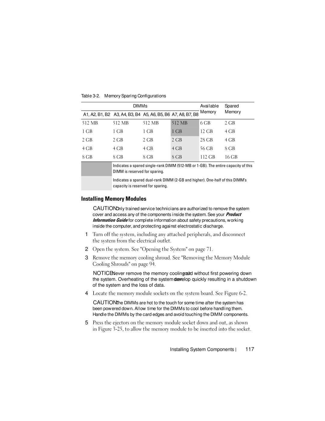
Memory Sparing Configurations DIMMs Available Spared
Installing Memory Modules
117
512 MB 12 GB 28 GB 56 GB 112 GB 16 GB
Socket Alignment keys
25. Installing and Removing a Memory Module Memory module
119
Removing Memory Modules
Integrated NIC TOE
Processors
Removing a Processor
121
26. Installing and Removing the Heat Sink Heat sink
123
Installing a Processor
Installing System Components
Replacing the System Battery
System Battery
System battery is a 3.0-volt V, coin-cell battery
Locate the battery socket. See System Board Connectors on
Installing System Components
Sideplane Board
Installing the Sideplane Board
Removing the Sideplane Board
127
128
Handle
SAS controller daughter card socket
SAS/SATA Backplane Board
Removing the SAS/SATA Backplane Board
129
Installing the SAS/SATA Backplane Board
Optical drive power connector Securing slots Securing tabs
SAS/SATA backplane board
Control Panel Assembly Service-only Procedure
Removing the Control Panel Assembly
131
Control panel circuit board
Display module Display module cable Control panel cable
Installing the Control Panel Assembly
System Board Service-only Procedure
Removing the System Board
133
Installing System Components
System-board tray
135
Installing the System Board
Management software Documentation Monitors power indicator
Safety First-For You and Your System
Start-Up Routine
137
Troubleshooting IRQ Assignment Conflicts
Checking the Equipment
138
Troubleshooting the Video Subsystem
Troubleshooting External Connections
Monitor is not working properly Video memory is faulty
139
Troubleshooting the Keyboard
Troubleshooting Basic I/O Functions
Troubleshooting the Mouse
141
Troubleshooting a Serial I/O Device
Troubleshooting a USB Device
Troubleshooting a NIC
NIC cannot communicate with network
143
Liquid spilled on the system Excessive humidity 144
Troubleshooting a Wet System
145
System was dropped or damaged
Troubleshooting a Damaged System
Troubleshooting the System Battery
Troubleshooting Power Supplies
147
Action
Troubleshooting System Cooling Problems
Troubleshooting a Fan
149
Troubleshooting System Memory
151
System cannot read data from an SD card or USB key
Troubleshooting an SD Card or Internal USB Key
153
Troubleshooting an Optical Drive
Troubleshooting an External Tape Drive
155
Troubleshooting a Hard Drive
Troubleshooting Your System
157
Troubleshooting a SAS Controller Daughter Card
Troubleshooting Expansion Cards
159
Troubleshooting the Microprocessors
System Diagnostics Features
Using Server Administrator Diagnostics
Running the System Diagnostics
When to Use the System Diagnostics
System Diagnostics Testing Options
162
Selecting Devices for Testing
Using the Custom Test Options
Selecting Diagnostics Options
163
Viewing Information and Results
Jumpers and Connectors
System Board Jumpers
165
Default system boot
Configuration settings are retained at
Password feature is disabled
System Board Connectors
System Board Jumper Settings Jumper SettingDescription
Default The password feature is enabled
168
System Board Connectors
169
SAS/SATA Backplane Board Connectors
Drive 0 connector Drive 1 connector
SAS connector SAS Jumpers and Connectors
171
System board connector
Sideplane Board Connectors
Expansion-Card Riser-Board Components and PCIe Buses
172
System board connector Length
Pin collars System board connector Jumpers and Connectors
173
Disabling a Forgotten Password
Contacting Dell
175
Getting Help
176
Amperes AC Alternating current
177
178
179
180
181
Hz Hertz
182
183
184
185
186
187
RAC Remote access controller
188
System diskette See bootable diskette
189
System memory See RAM
TCP/IP Transmission Control Protocol/Internet Protocol
VAC Volts alternating current VDC Volts direct current
190
191
192
Index
193
Index
Sideplane board, 127 system board, 136 USB memory key
195
Microprocessor See processor
197
Power supply, 79 system battery, 125 system board
Serial communications options
Troubleshooting tape drive USB device, 143 video
Upgrades processor
199
200