2. CONNECTOR LOCATION AND PIN LAYOUT
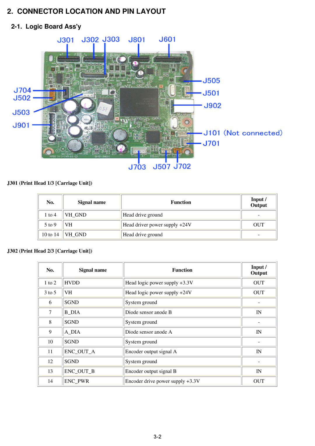
2-1. Logic Board Ass'y
J301 (Print Head 1/3 [Carriage Unit])
No. | Signal name | Function |
1 to 4 | VH_GND | Head drive ground |
5 to 9 | VH | Head driver power supply +24V |
10 to 14 | VH_GND | Head drive ground |
J302 (Print Head 2/3 [Carriage Unit])
Input / Output
-
OUT
-
No. | Signal name | Function | Input / | |
Output | ||||
|
|
| ||
1 to 2 | HVDD | Head logic power supply +3.3V | OUT | |
3 to 5 | VH | Head logic power supply +24V | OUT | |
6 | SGND | System ground | - | |
7 | B_DIA | Diode sensor anode B | IN | |
8 | SGND | System ground | - | |
9 | A_DIA | Diode sensor anode A | IN | |
10 | SGND | System ground | - | |
11 | ENC_OUT_A | Encoder output signal A | IN | |
12 | SGND | System ground | - | |
13 | ENC_OUT_B | Encoder output signal B | IN | |
14 | ENC_PWR | Encoder drive power supply +3.3V | OUT |