Matching 38AU Model To Evaporator Coil
The Model 38AUZ is a
The Model 38AUD is a
Evaluate the path and required line length for interconnecting refrigeration piping, including suction riser requirements (outdoor unit above indoor unit), liquid line lift (outdoor unit below indoor unit) and hot gas bypass line. Relocate sections to minimize the length of interconnecting tubing.
DO NOT BURY REFRIGERATION LINES.
Although unit is weatherproof, avoid locations that permit water from higher level runoff and overhangs to fall onto the unit.
Table 3 – Evaporator Coil Connections
Evaporator Coil has | Connect to Model | Notes |
|
|
|
Single Circuit | 38AUZ ONLY |
|
|
|
|
| 38AUZ | Manifold evaporator |
|
| circuits into single |
|
| piping system |
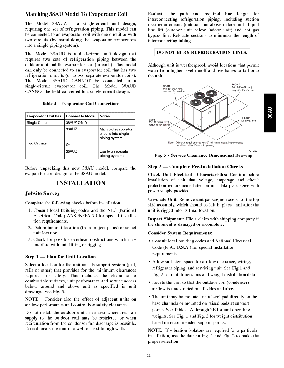
REAR:
Min 18” (457 mm) requried for service
LEFT:
Min 18” (457 mm) requried for service
RIGHT:
Min 18” (457 mm) requried for service
FRONT:
42” (1067 mm)
38AU
Two Circuits | Or |
|
|
| |
| 38AUD | Use two separate |
|
| piping systems |
Before unpacking this new 38AU model, compare the evaporator coil design to the 38AU model.
.INSTALLATION
Jobsite Survey
Complete the following checks before installation.
1.Consult local building codes and the NEC (National Electrical Code) ANSI/NFPA 70 for special installa- tion requirements.
2.Determine unit location (from project plans) or select unit location.
3.Check for possible overhead obstructions which may interfere with unit lifting or rigging.
Step 1 — Plan for Unit Location
Select a location for the unit and its support system (pad, rails or other) that provides for the minimum clearances required for safety. This includes the clearance to combustible surfaces, unit performance and service access below, around and above unit as specified in unit drawings. See Fig. 5.
NOTE: Consider also the effect of adjacent units on airflow performance and control box safety clearance.
Do not install the outdoor unit in an area where fresh air supply to the outdoor coil may be restricted or when recirculation from the condenser fan discharge is possible. Do not locate the unit in a well or next to high walls.
Note: Observe requirements for 39” (914 mm) operating clearance on either Left or Rear coil opening.
C10201
Fig. 5 - Service Clearance Dimensional Drawing
Step 2 — Complete Pre-Installation Checks
Check Unit Electrical Characteristics: Confirm before installation of unit that voltage, amperage and circuit protection requirements listed on unit data plate agree with power supply provided.
Inspect Shipment: File a claim with shipping company if the shipment is damaged or incomplete.
Consider System Requirements:
S Consult local building codes and National Electrical Code (NEC, U.S.A.) for special installation requirements.
S Allow sufficient space for airflow clearance, wiring, refrigerant piping, and servicing unit. See Fig.1 and Fig. 2 for unit dimensions and weight distribution data.
S Locate the unit so that the outdoor coil (condenser) airflow is unrestricted on all sides and above.
S The unit may be mounted on a level pad directly on the base channels or mounted on raised pads at support points. See Tables 1A through 2B for unit operating weights. See Fig. 1 and Fig. 2 for weight distribution based on recommended support points.
NOTE: If vibration isolators are required for a particular installation, use the data in Fig. 1 and Fig. 2 to make the proper selection.
11