CKT
2
CKT
1
CKT
2
CKT
1
Circuit 2
Connections
Circuit 1
Connections
C10355
Fig. 6 - 38AUD Service Valve Locations
Plan the Circuit 1 and Circuit 2 tubing segments carefully, mark each segment and check constantly as piping systems are assembled to avoid piping errors.
38AUD unit cannot be
Connecting 40RU to 38AUD: The 40RU fan coil in sizes 16, 25 and 28 is a
Note that refrigerant suction piping should be insulated.
40RU | Cooling | 40RU Coil | Connect to | |
Arrangement | Stage | Segment | 38AUD | |
|
|
|
| |
Vertical | Y1 | 2 | Circuit 1 | |
Y2 | 1 | Circuit 2 | ||
| ||||
|
|
|
| |
Horizontal | Y1 | 1 | Circuit 1 | |
Y2 | 2 | Circuit 2 | ||
| ||||
|
|
|
|
Install Filter Drier(s) and Moisture Indicator(s) —
Every unit MUST have a filter drier in the liquid line. 38AUD models require two filter driers (one in each liquid line). Locate the filter drier(s) at the indoor unit, close to the evaporator coil’s thermal expansion valve (TXV) inlets.
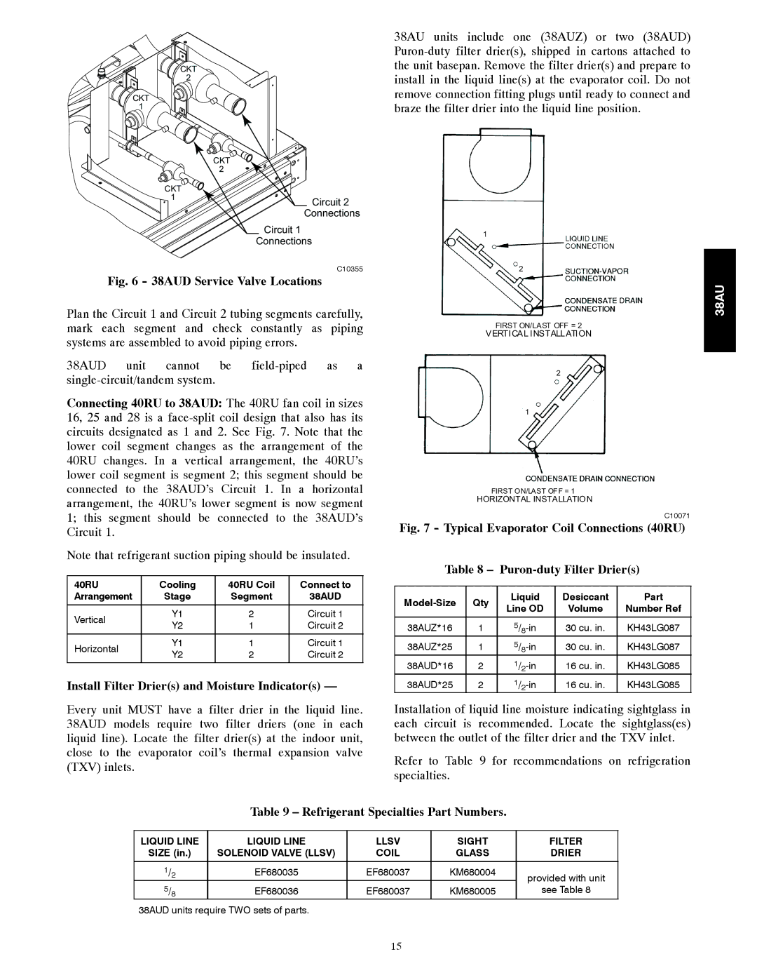
38AU units include one (38AUZ) or two (38AUD)
1
2
FIRST ON/LAST OFF = 2
VERTICAL INSTALLATION
2
1
FIRST ON/LAST OFF = 1
HORIZONTAL INSTALLATION
C10071
Fig. 7 - Typical Evaporator Coil Connections (40RU)
Table 8 – |
| ||||
|
|
|
|
| |
| Qty | Liquid | Desiccant | Part | |
Line OD | Volume | Number Ref | |||
|
| ||||
38AUZ*16 | 1 | 30 cu. in. | KH43LG087 | ||
38AUZ*25 | 1 | 30 cu. in. | KH43LG087 | ||
38AUD*16 | 2 | 16 cu. in. | KH43LG085 | ||
38AUD*25 | 2 | 16 cu. in. | KH43LG085 | ||
Installation of liquid line moisture indicating sightglass in each circuit is recommended. Locate the sightglass(es) between the outlet of the filter drier and the TXV inlet.
Refer to Table 9 for recommendations on refrigeration specialties.
38AU
Table 9 – Refrigerant Specialties Part Numbers.
LIQUID LINE | LIQUID LINE | LLSV | SIGHT | FILTER | |
SIZE (in.) | SOLENOID VALVE (LLSV) | COIL | GLASS | DRIER | |
|
|
|
|
|
|
1/ | 2 | EF680035 | EF680037 | KM680004 | provided with unit |
|
|
|
|
| |
5/8 | EF680036 | EF680037 | KM680005 | see Table 8 | |
38AUD units require TWO sets of parts.
15