Carrier 38AU appendix Power Wiring Connections, Convenience Outlets, Electrical Operation Hazard

Models: 38AU

1 56
Download 56 pages 45.1 Kb
Page 19
Image 19
Fig. 12 - Power Wiring Connections

Units Without Disconnect Option

C TB1

11 13

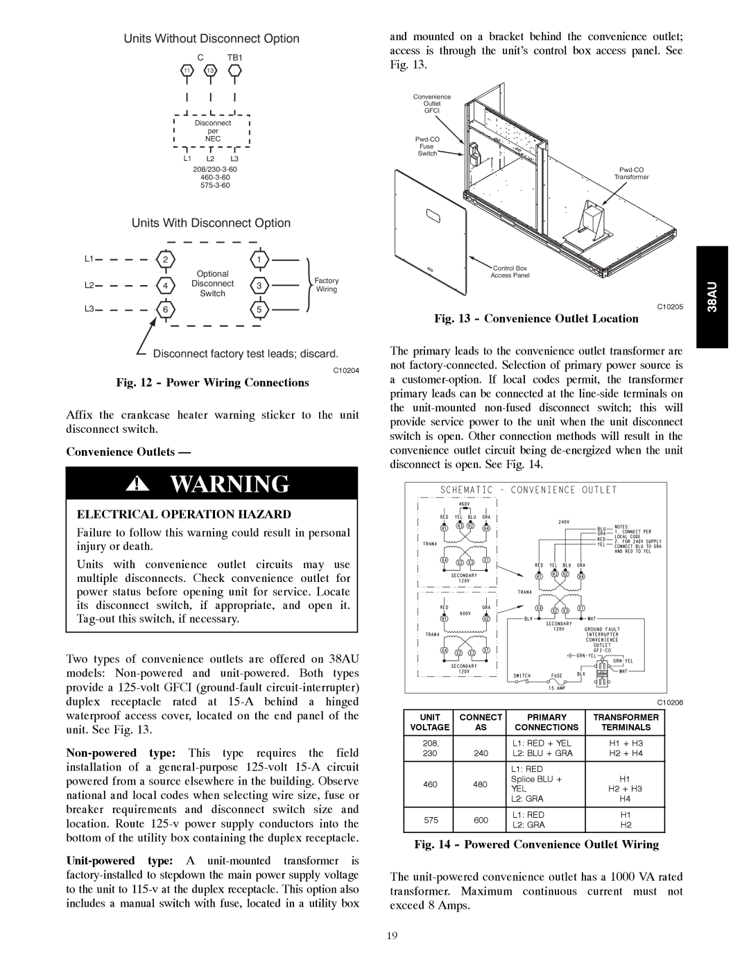
and mounted on a bracket behind the convenience outlet; access is through the unit’s control box access panel. See Fig. 13.

Disconnect

per

NEC

L1 L2 L3

208/230-3-60

460-3-60

575-3-60

Units With Disconnect Option

L1

2

1


Optional


Factory

Convenience

Outlet

GFCI

Pwd-CO

Fuse

SwitchConvenience Outlets —

ELECTRICAL OPERATION HAZARD Control Box

Access Panel

Pwd-CO

Transformer

L2

4

Disconnect

3

Wiring


Switch


L3

6


5


Disconnect factory test leads; discard.

C10204

Fig. 12 - Power Wiring Connections

Affix the crankcase heater warning sticker to the unit disconnect switch.

Convenience Outlets —

!WARNING

ELECTRICAL OPERATION HAZARD

Failure to follow this warning could result in personal injury or death.

Units with convenience outlet circuits may use multiple disconnects. Check convenience outlet for power status before opening unit for service. Locate its disconnect switch, if appropriate, and open it. Tag-out this switch, if necessary.

Two types of convenience outlets are offered on 38AU models: Non-powered and unit-powered. Both types provide a 125-volt GFCI (ground-fault circuit-interrupter) duplex receptacle rated at 15-A behind a hinged waterproof access cover, located on the end panel of the unit. See Fig. 13.

Non-powered type: This type requires the field installation of a general-purpose 125-volt 15-A circuit powered from a source elsewhere in the building. Observe national and local codes when selecting wire size, fuse or breaker requirements and disconnect switch size and location. Route 125-v power supply conductors into the bottom of the utility box containing the duplex receptacle.

Unit-powered type: A unit-mounted transformer is factory-installed to stepdown the main power supply voltage to the unit to 115-v at the duplex receptacle. This option also includes a manual switch with fuse, located in a utility box

C10205

Fig. 13 - Convenience Outlet Location

The primary leads to the convenience outlet transformer are not factory-connected. Selection of primary power source is a customer-option. If local codes permit, the transformer primary leads can be connected at the line-side terminals on the unit-mounted non-fused disconnect switch; this will provide service power to the unit when the unit disconnect switch is open. Other connection methods will result in the convenience outlet circuit being de-energized when the unit disconnect is open. See Fig. 14.


C10206

UNIT

CONNECT

PRIMARY

TRANSFORMER

VOLTAGE

AS

CONNECTIONS

TERMINALS

208,


L1: RED + YEL

H1 + H3

230

240

L2: BLU + GRA

H2 + H4


L1: RED


460

480

Splice BLU +

H1

YEL

H2 + H3


L2: GRA

H4


575

600

L1: RED

H1

L2: GRA

H2


Fig. 14 - Powered Convenience Outlet Wiring

The unit-powered convenience outlet has a 1000 VA rated transformer. Maximum continuous current must not exceed 8 Amps.

38AU

19

Page 19
Image 19
Carrier 38AU Power Wiring Connections, Convenience Outlets, Electrical Operation Hazard, Convenience Outlet Location