Manuals
/
Carrier
/
Household Appliance
/
Air Conditioner
Carrier
appendix
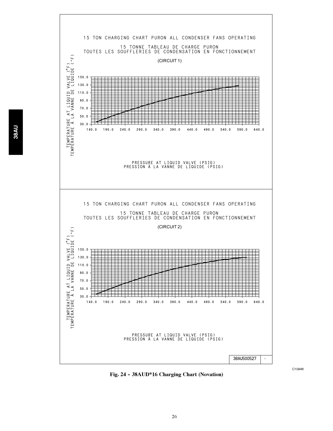
38AUD*16 Charging Chart Novation
Models:
38AU
1
26
56
56
Download
56 pages
45.1 Kb
23
24
25
26
27
28
29
30
Troubleshooting
Install
38AUZ*16 Charging Chart Rtpf
Field Control Wiring
Dimension
Maintenance
Field Refrigerant Access Ports
Adjust Refrigerant Charge
Checklist
Safety
Page 26
Image 26
38AU
(CIRCUIT 1)
(CIRCUIT 2)
C10946
Fig. 24 - 38AUD*16 Charging Chart (Novation)
26
Page 25
Page 27
Page 26
Image 26
Page 25
Page 27
Contents
Installation, Start---Up Service Instructions
Contents
Replacement/Retrofit R-22 to PuronR
Safety Considerations
Installation Guideline
Installation
Unit Damage Hazard
Rtpf
Unit
Mchx
38AUZ*25
38AUD*25
Compressor
Unit Size 38AU
Refrigerant TYPE‡
Condenser Fans
Rtpf Shipping Charge kg
Pressurestat Settings kPa High Cutout
Nominal Capacity kW
Scroll
Face Area sq ft total Rows/Fins per inch FPI
Rtpf Shipping Charge A/B lb
Oil Charge A/B oz
Oil Charge A/B L
Operating Weight kg Novation Coil Al Tube
Rtpf Shipping Charge A/B kg
Qty...r/s Motor Hp Nema Diameter mm
U Z a 2 5 a 0 G 6 a 0 a 0 a
Jobsite Survey
Installation
Matching 38AU Model To Evaporator Coil
Do not Bury Refrigeration Lines
Equivalent Lengths for Common Fittings ft
Provide Safety Relief
Slab Mount
Check 38AU Model with Evaporator Coil Connections
38AUZ 16-25 Piping Recommendations Single-Circuit Unit
Liquid Lift
Suction Riser
Insulate Suction Lines
38AUD 16-25 Piping Recommendations Two-Circuit Unit
Vertical Separation outdoor unit above indoor unit
Hot Gas Bypass
Install Filter Driers and Moisture Indicators
Refrigerant Specialties Part Numbers
Selecting an Accumulator
Install Liquid Line Solenoid Valve
Capacity Control Liquid Line Solenoid Valve
Make Piping Connections
Evacuation/Dehydration
Preliminary Charge
Fire Hazard
Field Power Supply
Units with Factory-Installed Disconnect
All Units
Convenience Outlets
Electrical Operation Hazard
Field Control Wiring
Convenience Outlet Utilization Notice Label
Control Transformer Wiring
Thermostat
Unit Wire/Fuse or Hacr Breaker Sizing Data
Unbalanced 3-Phase Supply Voltage
System Check
PRE-START-UP
START-UP
Preliminary Checks
Using plotted operating point
Advanced Scroll Temperature Protection Astp
Adjust Refrigerant Charge
Start Unit
38AUZ*25 Check Compressor Oil Level
Final Checks
38AUD*16 Charging Chart Novation
38AUZ*16 Charging Chart Rtpf
38AUD*16 Charging Chart Rtpf
38AUD*25 Charging Chart Rtpf
Typical 38AUZ Wiring Diagram 15 Ton 230V Tandem Unit Shown
Typical 38AUD Wiring Diagram 15 Ton 230V Dual Unit Shown
Operating Sequence
Base Unit Controls
Refrigeration System
Routine System Maintenance
Service
Equipment Damage Hazard
Liquid Line Filter Drier
Field Refrigerant Access Ports
Factory High-Flow Access Ports
Comfort Alert Diagnostic Module
Input Terminal Voltage
LED Status Codes
Lockout
Compressor Protection
38AUD Size 16 Cabinet
LPS
38AUZ,D Size 25 Cabinet
38AUZ*25 Compressor Assembly Rear View
Coil Type Identification
Novation Coil Cleaning and Maintenance
Repairing Novation Condenser Tube Leaks
NOVATIONt Type
Unit Reliability Hazard
Routine Cleaning of Round-Tube Plate Fin Rtpf Coils
Replacing NOVATIONt Condenser Coil
Compressor Stops on HIGH-PRESSURE Switch
Troubleshooting
Problem Solution Compressor does not RUN
Fastener Torque Values
Unit Operates TOO Long or Continuously
Problem Solution Compressor Cycles on LOW-PRESSURE Switch
Compressor Running but Cooling Insufficient
System is Noisy
Appendix B
Wiring Diagram List
Appendix a
Appendix C
Low Ambient Option Factory Installed
Troubleshooting
Operation
Motormaster Sensor Location
38AUZ*16 & 38AUD*16 Novation 38AUZ*16/25 & 38AUD*16/25 Rtpf
Dimensions --- MM Unit Baffle
Wind Baffle Dimension
Dimensions --- Inches Unit Baffle
Wind Baffles Fabrication
15 Ton Wind Baffle Brackets Fabrication
Front
Front Back Left Right
Catalog No 38AU---09SI
START-UP Checklist
II. PRE-START-UP Outdoor Unit
Check Voltage Imbalance
Top
Page
Image
Contents