38AU
Step 7 — Complete Electrical Connections
!WARNING
ELECTRICAL SHOCK HAZARD
Failure to follow this warning could result in personal injury or death.
Do not use gas piping as an electrical ground. Unit cabinet must have an uninterrupted, unbroken electrical ground to minimize the possibility of personal injury if an electrical fault should occur. This ground may consist of electrical wire connected to unit ground lug in control compartment, or conduit approved for electrical ground when installed in accordance with NEC (National Electrical Code); ANSI/NFPA 70, latest edition (in Canada, Canadian Electrical Code CSA [Canadian Standards Association] C22.1), and local electrical codes.
NOTE: Check all factory and field electrical connections for tightness.
Field Power Supply —
If equipped with optional Powered Convenience Outlet: The power source leads to the convenience outlet’s transformer primary are not factory connected. Installer must connect these leads according to required operation of the convenience outlet. If an
Field power wires are connected to the unit at
NOTE: TEST LEADS - Unit may be equipped with short leads (pigtails) on the field line connection points on contactor C or optional disconnect switch. These leads are for factory
!WARNING
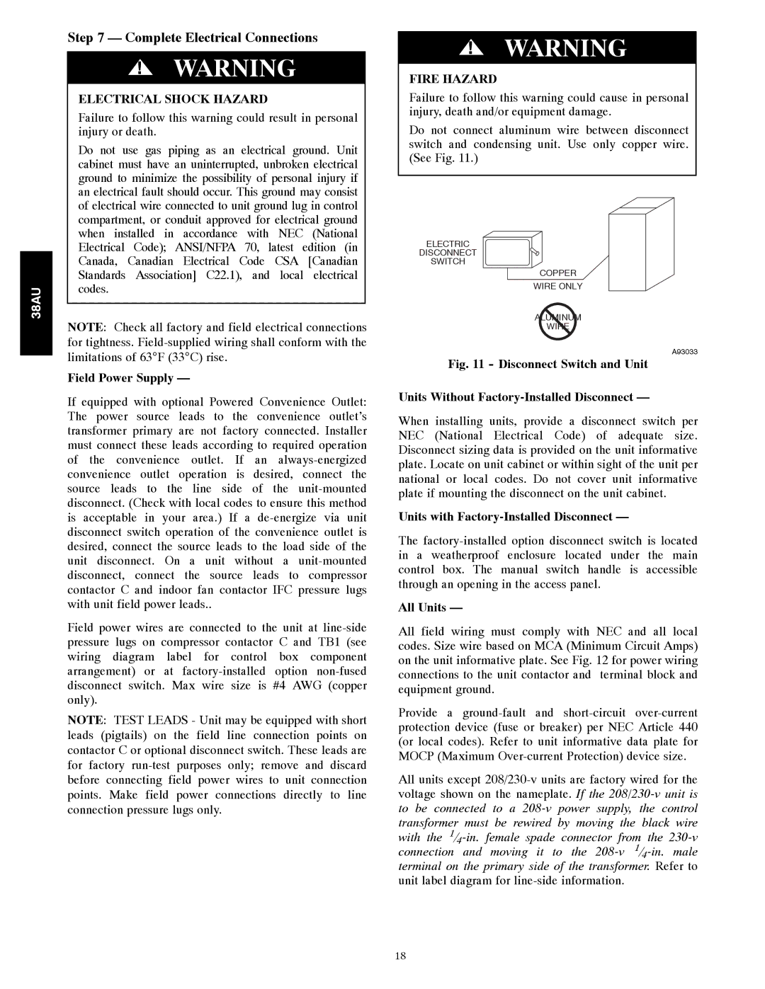
FIRE HAZARD
Failure to follow this warning could cause in personal injury, death and/or equipment damage.
Do not connect aluminum wire between disconnect switch and condensing unit. Use only copper wire. (See Fig. 11.)
ELECTRIC
DISCONNECT
SWITCH
COPPER
WIRE ONLY
ALUMINUM
WIRE
A93033
Fig. 11 - Disconnect Switch and Unit
Units Without Factory-Installed Disconnect —
When installing units, provide a disconnect switch per NEC (National Electrical Code) of adequate size. Disconnect sizing data is provided on the unit informative plate. Locate on unit cabinet or within sight of the unit per national or local codes. Do not cover unit informative plate if mounting the disconnect on the unit cabinet.
Units with Factory-Installed Disconnect —
The
All Units —
All field wiring must comply with NEC and all local codes. Size wire based on MCA (Minimum Circuit Amps) on the unit informative plate. See Fig. 12 for power wiring connections to the unit contactor and terminal block and equipment ground.
Provide a
All units except
18