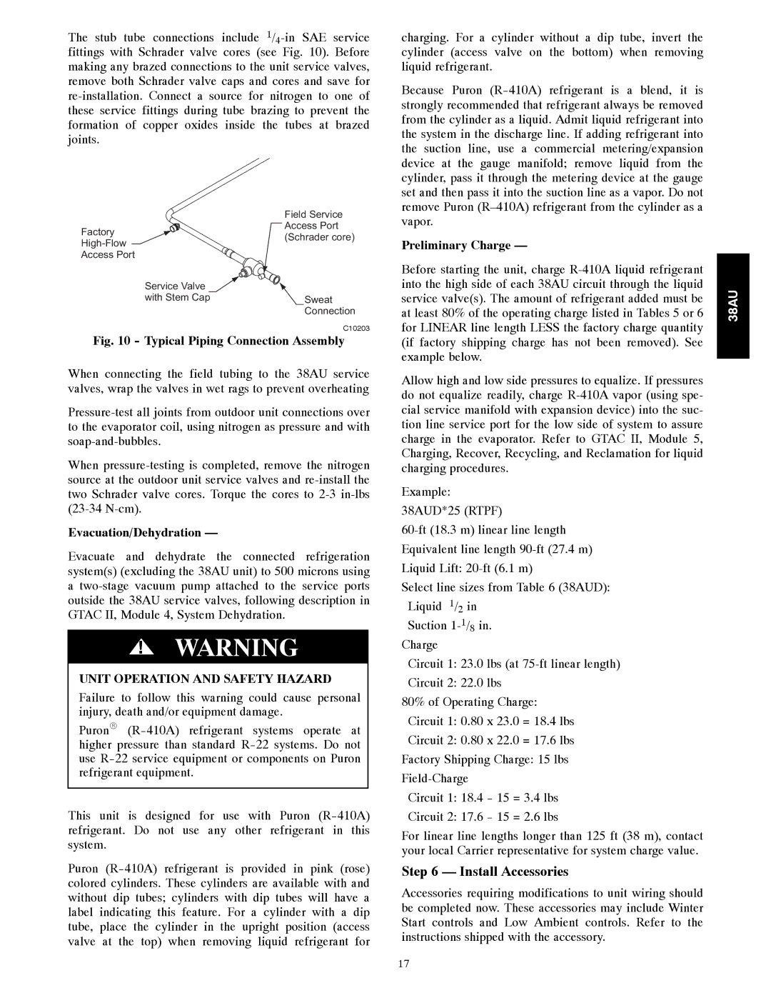
The stub tube connections include 1/4-in SAE service fittings with Schrader valve cores (see Fig. 10). Before making any brazed connections to the unit service valves, remove both Schrader valve caps and cores and save for re-installation. Connect a source for nitrogen to one of these service fittings during tube brazing to prevent the formation of copper oxides inside the tubes at brazed joints.
| | Field Service |
| Factory | Access Port |
| (Schrader core) |
| High-Flow |
| |
| Access Port | |
| Service Valve | |
| with Stem Cap | Sweat |
| | Connection |
C10203
Fig. 10 - Typical Piping Connection Assembly
When connecting the field tubing to the 38AU service valves, wrap the valves in wet rags to prevent overheating
Pressure-test all joints from outdoor unit connections over to the evaporator coil, using nitrogen as pressure and with soap-and-bubbles.
When pressure-testing is completed, remove the nitrogen source at the outdoor unit service valves and re-install the two Schrader valve cores. Torque the cores to 2-3 in-lbs (23-34 N-cm).
Evacuation/Dehydration —
Evacuate and dehydrate the connected refrigeration system(s) (excluding the 38AU unit) to 500 microns using a two-stage vacuum pump attached to the service ports outside the 38AU service valves, following description in GTAC II, Module 4, System Dehydration.
!WARNING
UNIT OPERATION AND SAFETY HAZARD
Failure to follow this warning could cause personal injury, death and/or equipment damage.
PuronR (R-410A) refrigerant systems operate at higher pressure than standard R-22 systems. Do not use R-22 service equipment or components on Puron refrigerant equipment.
This unit is designed for use with Puron (R-410A) refrigerant. Do not use any other refrigerant in this system.
Puron (R-410A) refrigerant is provided in pink (rose) colored cylinders. These cylinders are available with and without dip tubes; cylinders with dip tubes will have a label indicating this feature. For a cylinder with a dip tube, place the cylinder in the upright position (access valve at the top) when removing liquid refrigerant for
charging. For a cylinder without a dip tube, invert the cylinder (access valve on the bottom) when removing liquid refrigerant.
Because Puron (R-410A) refrigerant is a blend, it is strongly recommended that refrigerant always be removed from the cylinder as a liquid. Admit liquid refrigerant into the system in the discharge line. If adding refrigerant into the suction line, use a commercial metering/expansion device at the gauge manifold; remove liquid from the cylinder, pass it through the metering device at the gauge set and then pass it into the suction line as a vapor. Do not remove Puron (R–410A) refrigerant from the cylinder as a vapor.
Preliminary Charge —
Before starting the unit, charge R-410A liquid refrigerant into the high side of each 38AU circuit through the liquid service valve(s). The amount of refrigerant added must be at least 80% of the operating charge listed in Tables 5 or 6 for LINEAR line length LESS the factory charge quantity (if factory shipping charge has not been removed). See example below.
Allow high and low side pressures to equalize. If pressures do not equalize readily, charge R-410A vapor (using spe- cial service manifold with expansion device) into the suc- tion line service port for the low side of system to assure charge in the evaporator. Refer to GTAC II, Module 5, Charging, Recover, Recycling, and Reclamation for liquid charging procedures.
Example: 38AUD*25 (RTPF)
60-ft (18.3 m) linear line length Equivalent line length 90-ft (27.4 m) Liquid Lift: 20-ft (6.1 m)
Select line sizes from Table 6 (38AUD): Liquid 1/2 in
Suction 1-1/8in. Charge
Circuit 1: 23.0 lbs (at 75-ft linear length)
Circuit 2: 22.0 lbs
80% of Operating Charge: Circuit 1: 0.80 x 23.0 = 18.4 lbs Circuit 2: 0.80 x 22.0 = 17.6 lbs Factory Shipping Charge: 15 lbs Field-Charge
Circuit 1: 18.4 - 15 = 3.4 lbs
Circuit 2: 17.6 - 15 = 2.6 lbs
For linear line lengths longer than 125 ft (38 m), contact your local Carrier representative for system charge value.
Step 6 — Install Accessories
Accessories requiring modifications to unit wiring should be completed now. These accessories may include Winter Start controls and Low Ambient controls. Refer to the instructions shipped with the accessory.