38AU
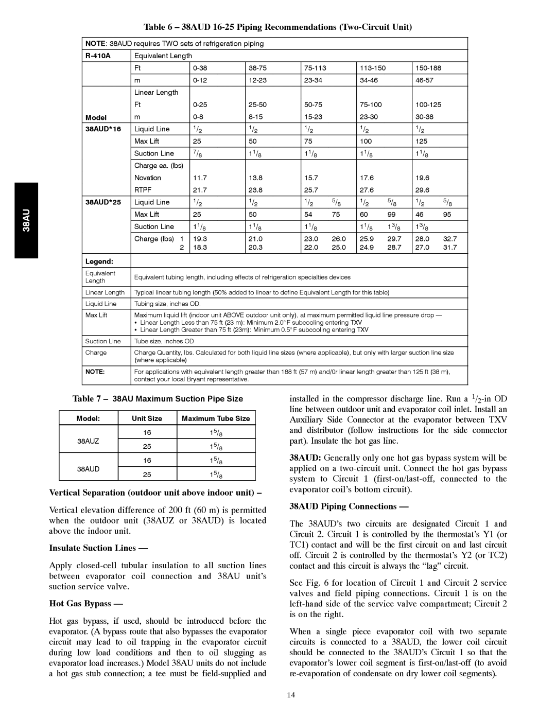
Table 6 – 38AUD 16-25 Piping Recommendations (Two-Circuit Unit)
NOTE: 38AUD requires TWO sets of refrigeration piping
| Equivalent Length |
|
|
|
|
|
|
|
| ||
|
|
|
|
|
|
|
|
|
|
|
|
| Ft |
|
|
|
|
| |||||
|
|
|
|
|
|
|
|
|
|
|
|
| m |
|
|
|
|
| |||||
|
|
|
|
|
|
|
|
|
|
| |
| Linear Length |
|
|
|
|
|
|
|
|
| |
| Ft |
|
|
|
|
| |||||
Model | m |
|
|
|
|
| |||||
38AUD*16 | Liquid Line |
| 1/2 | 1/2 | 1/2 |
| 1/2 |
| 1/2 |
| |
| Max Lift |
| 25 | 50 | 75 |
| 100 |
| 125 |
| |
|
|
|
|
|
|
|
|
|
|
| |
| Suction Line |
| 7/8 | 11/8 | 11/8 |
| 11/8 |
| 11/8 |
| |
| Charge ea. (lbs) |
|
|
|
|
|
|
|
|
| |
| Novation |
| 11.7 | 13.8 | 15.7 |
| 17.6 |
| 19.6 |
| |
| RTPF |
| 21.7 | 23.8 | 25.7 |
| 27.6 |
| 29.6 |
| |
|
|
|
|
|
|
|
|
|
|
| |
38AUD*25 | Liquid Line |
| 1/2 | 1/2 | 1/2 | 5/8 | 1/2 | 5/8 | 1/2 | 5/8 | |
| Max Lift |
| 25 | 50 | 54 | 75 | 60 | 99 | 46 | 95 | |
|
|
|
|
|
|
|
|
|
|
| |
| Suction Line |
| 11/8 | 11/8 | 11/8 |
| 11/8 | 13/8 | 13/8 |
| |
| Charge (lbs) 1 |
| 19.3 | 21.0 | 23.0 | 26.0 | 25.9 | 29.7 | 28.0 | 32.7 | |
|
| 2 |
| 18.3 | 20.3 | 22.0 | 25.0 | 24.9 | 28.7 | 27.0 | 31.7 |
|
|
|
|
|
|
|
|
|
|
|
|
Legend: |
|
|
|
|
|
|
|
|
|
|
|
|
|
|
|
|
|
|
|
|
|
|
|
Equivalent | Equivalent tubing length, including effects of refrigeration specialties devices |
|
|
|
| ||||||
Length |
|
|
|
| |||||||
|
|
|
|
|
|
|
|
|
|
| |
|
|
|
| ||||||||
Linear Length | Typical linear tubing length (50% added to linear to define Equivalent Length for this table) |
|
| ||||||||
|
|
|
|
|
|
|
|
| |||
Liquid Line | Tubing size, inches OD. |
|
|
|
|
|
|
| |||
|
|
| |||||||||
Max Lift | Maximum liquid lift (indoor unit ABOVE outdoor unit only), at maximum permitted liquid line pressure drop — |
| |||||||||
| S | Linear Length Less than 75 ft (23 m): Minimum 2.0° F subcooling entering TXV |
|
|
| ||||||
| S | Linear Length Greater than 75 ft (23m): Minimum 0.5° F subcooling entering TXV |
|
|
| ||||||
|
|
|
|
|
|
|
|
| |||
Suction Line | Tube size, inches OD |
|
|
|
|
|
|
| |||
|
| ||||||||||
Charge | Charge Quantity, lbs. Calculated for both liquid line sizes (where applicable), but only with larger suction line size | ||||||||||
| (where applicable) |
|
|
|
|
|
|
|
| ||
|
| ||||||||||
NOTE: | For applications with equivalent length greater than 188 ft (57 m) and/0r linear length greater than 125 ft (38 m), | ||||||||||
| contact your local Bryant representative. |
|
|
|
|
|
| ||||
|
|
|
|
|
|
|
|
|
|
|
|
Table 7 – 38AU Maximum Suction Pipe Size
Model: | Unit Size | Maximum Tube Size | |
|
|
| |
38AUZ | 16 | 15/8 | |
25 | 15/8 | ||
| |||
38AUD | 16 | 15/8 | |
25 | 15/8 | ||
|
Vertical Separation (outdoor unit above indoor unit) –
Vertical elevation difference of 200 ft (60 m) is permitted when the outdoor unit (38AUZ or 38AUD) is located above the indoor unit.
Insulate Suction Lines —
Apply
Hot Gas Bypass —
Hot gas bypass, if used, should be introduced before the evaporator. (A bypass route that also bypasses the evaporator circuit may lead to oil trapping in the evaporator circuit during low load conditions and then to oil slugging as evaporator load increases.) Model 38AU units do not include a hot gas stub connection; a tee must be
installed in the compressor discharge line. Run a
38AUD: Generally only one hot gas bypass system will be applied on a
38AUD Piping Connections —
The 38AUD’s two circuits are designated Circuit 1 and Circuit 2. Circuit 1 is controlled by the thermostat’s Y1 (or TC1) contact and will be the first circuit on and last circuit off. Circuit 2 is controlled by the thermostat’s Y2 (or TC2) contact and this circuit is always the “lag” circuit.
See Fig. 6 for location of Circuit 1 and Circuit 2 service valves and field piping connections. Circuit 1 is on the
When a single piece evaporator coil with two separate circuits is connected to a 38AUD, the lower coil circuit should be connected to the 38AUD’s Circuit 1 so that the evaporator’s lower coil segment is
14