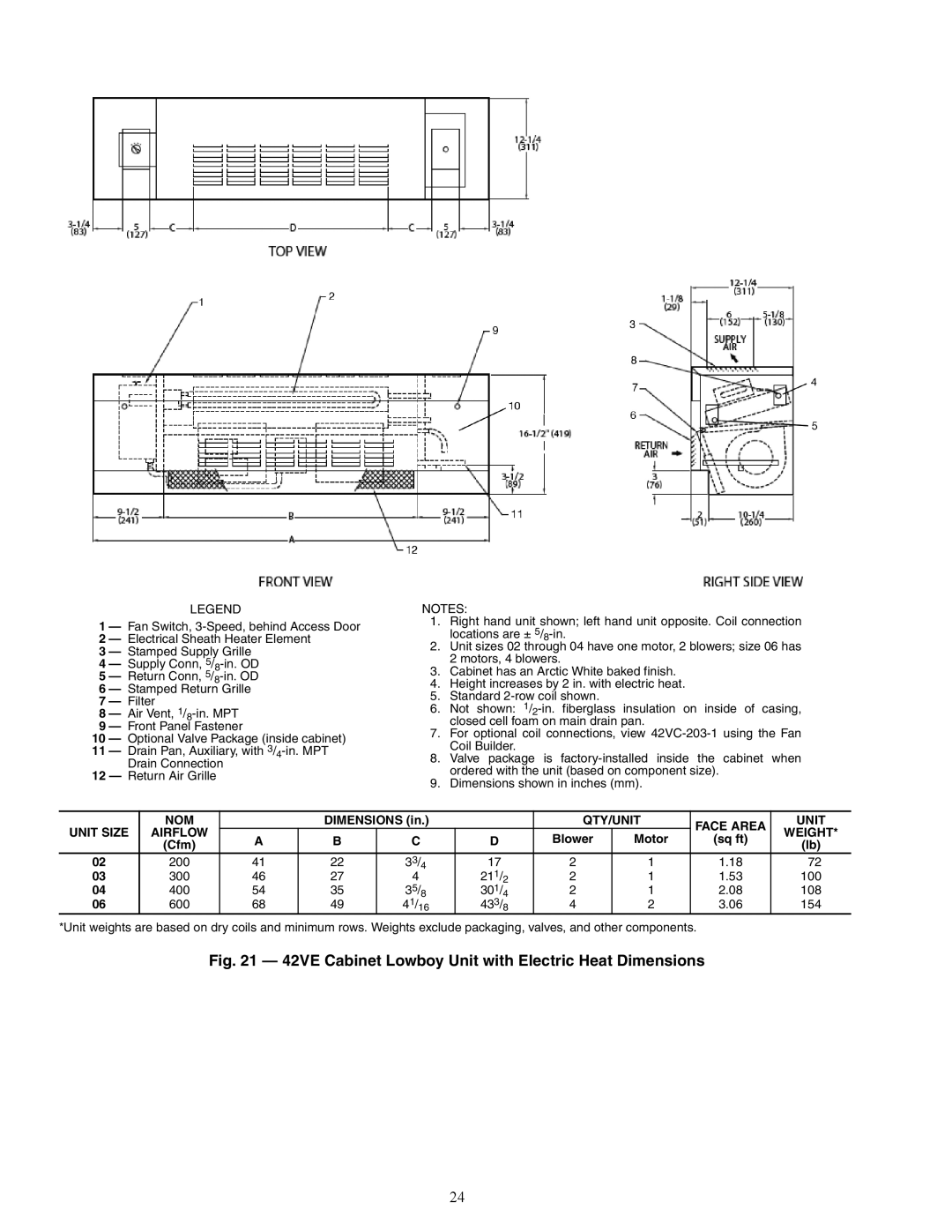
42V, 42D, 42S, 42C specifications
Carrier has established itself as a leader in the HVAC industry by continuously innovating and refining their products. Among their offerings, the Carrier 42D, 42C, 42S, and 42V series stand out for their advanced features, efficient technologies, and user-friendly characteristics.The Carrier 42D series is known for its robust and energy-efficient design, making it ideal for commercial applications. This series employs a high-performance scroll compressor that enhances efficiency while minimizing noise levels. Equipped with advanced controls, the 42D allows for precise temperature management, ensuring comfort in a variety of environments. Its compact design is another notable feature, allowing for easier installation in constrained spaces while still delivering excellent performance.
Similar to the 42D, the 42C series emphasizes energy efficiency, but it comes with additional features tailored for residential applications. One of the main highlights is its variable-speed compressor technology, which provides exceptional temperature control and reduces energy consumption. This series also includes enhanced filtration systems, ensuring cleaner air quality, which is particularly important for allergy sufferers. Moreover, the 42C's intelligent control systems simplify operation and allow users to customize settings according to their preferences.
The Carrier 42S series focuses on environmentally friendly refrigerants, aligning with global sustainability trends. This series utilizes R-410A refrigerant, which has a lower impact on the ozone layer compared to traditional refrigerants. In addition to its eco-friendly attributes, the 42S boasts features such as an integrated humidity control system, which modulates humidity levels effectively, improving overall indoor air quality.
Finally, the 42V series presents a versatile solution for customers looking for advanced technology and adaptability. With smart connectivity features, the 42V allows for remote monitoring and control via mobile apps, enhancing user convenience. This series is also equipped with a state-of-the-art inverter compressor, which adjusts its speed according to the heating or cooling demand, resulting in significant energy savings.
In summary, the Carrier 42D, 42C, 42S, and 42V series each offer unique features and technological advancements that cater to the diverse needs of users in both residential and commercial settings. With a focus on energy efficiency, user-friendly controls, and environmentally sustainable practices, Carrier continues to set the standard in HVAC solutions.

