Carrier 42V, 42C, 42S, 42D specifications Pre-Installation

Models: 42V 42D 42S 42C

1 72
Download 72 pages 52.3 Kb
Page 3
Image 3

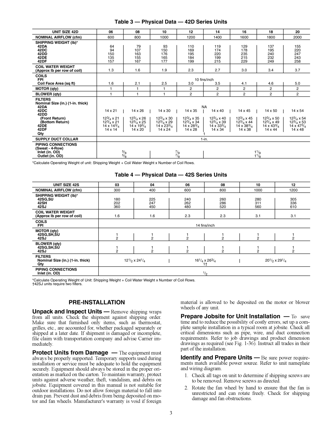
Table 3 — Physical Data — 42D Series Units

UNIT SIZE 42D

06


08


10


12


14


16


18


20


NOMINAL AIRFLOW (cfm)

600


800


1000


1200


1400


1600


1800


2000


SHIPPING WEIGHT (lb)*


42DA


64


79


93


110


119


129


137


155


42DC


94


107


150


169


174


178


195


220


42DD

150


163


176


195


220


235


240


247


42DE

135


155


165


184


199


215


232


243


42DF

157


167


177


199


215


229


249


258


COIL WATER WEIGHT

1.3


1.6


1.9


2.3


2.7


3.0


3.4


3.7


(Approx lb per row of coil)


COILS


FPI


10 fins/inch


Coil Face Area (sq ft)

1.6


2.1


2.5


3.0


3.5


4.1


4.6


5.0


MOTOR (qty)


1


1


1


2


2


2


2


2


BLOWER (qty)


1


1


1


2


2


2


2


2


FILTERS


Nominal Size (in.) (1-in. thick)


42DA


NA


42DC

14 x 21


14 x 26


14 x 30


14 x 35


14 x 40


14 x 45


14 x 50


14 x 54


42DD

123/


123/


123/


123/


123/


123/


123/


123/


(Front Return)

4

x 21


4

x 26


4

x 30


4

x 35


4

x 40


4

x 45


4

x 50


4

x 54


(Bottom Return)

123/

x 21


123/

x 25


123/

x 29


123/

x 34


123/

x 39


123/

x 44


123/

x 49


123/

x 53

4


4


4


4


4


4


4


4

42DE

14 x 143/

4


14 x 193/


14 x 233/

4


14 x 283/


14 x 333/


14 x 383/


14 x 433/


14 x 473/

4

42DF

14 x 14


4


14 x 24


4


4


4


4


14 x 48


14 x 20


14 x 28


14 x 34


14 x 38


14 x 44


Qty


1


SUPPLY DUCT COLLAR


1-in.


PIPING CONNECTIONS


(Sweat - 4-Row)


5/


7/


11/


Inlet (in. OD)


8


Outlet (in. OD)


5/


8


8


8


7/


11/


8


8


*Calculate Operating Weight of unit: Shipping Weight + Coil Water Weight x Number of Coil Rows.

Table 4 — Physical Data — 42S Series Units

UNIT SIZE 42S

03


04


06


08


10


12

NOMINAL AIRFLOW (cfm)

300


400


600


800


1000


1200

SHIPPING WEIGHT (lb)*


42SG,SU

180


225


240


260


280


305


42SH

202


247


262


286


311


336

42SJ

360


450


480


520


560


610

COIL WATER WEIGHT


(Approx lb per row of coil)

1.6


1.6


2.3


2.3


3.1


3.1

COILS


FPI


14 fins/inch


MOTOR (qty)


42SG,SH,SU

1


1


1


1


1


1


42SJ

2


2


2


2


2


2

BLOWER (qty)


42SG,SH,SU

1


1


1


1


1


1


42SJ

2


2


2


2


2


2

FILTERS

121/

x 241/


161/

x 263/


201/

x 291/

Nominal Size (in.) (1-in. thick)


4


Qty

2

4


4


2

4


1†


PIPING CONNECTIONS


1/2


Inlet (in. OD)


*Calculate Operating Weight of Unit: Shipping Weight + Coil Water Weight x Number of Coil Rows. †42SJ units require two filters.

PRE-INSTALLATION

Unpack and Inspect Units — Remove shipping wraps from all units. Check the shipment against shipping order. Make sure that furnished only items, such as thermostat, grilles, etc., are accounted for, whether packaged separately or shipped at a later date. If shipment is damaged or incomplete, file claim with transportation company and advise Carrier im- mediately.

Protect Units from Damage — The equipment must always be properly supported. Temporary supports used during installation or service must be adequate to hold the equipment securely. Equipment should always be stored in the proper ori- entation as marked on the carton. To maintain warranty, protect units against adverse weather, theft, vandalism, and debris on jobsite. Equipment covered in this manual is not suitable for outdoor installations. Do not allow foreign material to fall into drain pan. Prevent dust and debris from being deposited on mo- tor and fan wheels. Manufacturer's warranty is void if foreign

material is allowed to be deposited on the motor or blower wheels of any unit.

Prepare Jobsite for Unit Installation — To save time and to reduce the possibility of costly errors, set up a com- plete sample installation in a typical room at jobsite. Check all critical dimensions such as pipe, wire, and duct connection requirements. Refer to job drawings and product dimension drawings as required (see Fig. 1-36). Instruct all trades in their part of the installation.

Identify and Prepare Units — Be sure power require- ments match available power source. Refer to unit nameplate and wiring diagram.

1.Check all tags on unit to determine if shipping screws are to be removed. Remove screws as directed.

2.Rotate the fan wheel by hand to ensure that the fan is unrestricted and can rotate freely. Check for shipping damage and fan obstructions.

3

Page 3
Image 3
Carrier 42V, 42C, 42S, 42D specifications Pre-Installation