Appendix D Connecting DC Power
Connecting DC Power to a CDE200
Connecting DC Power to a CDE200
The CDE200 ships fully populated with two DC PMs installed in the PM slots on the rear of the chassis; two DC power cables are shipped separately. The chassis has one building ground stud and one PM ground stud. The minimum cabling requirement for connecting DC power to a CDE200 is one PM connect, but it is recommended that you use both PM connects. Figure
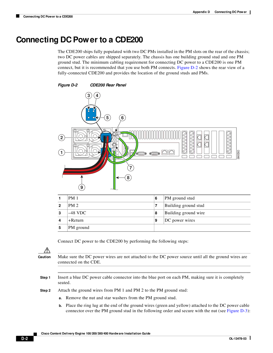
Figure D-2 CDE200 Rear Panel
3 4
5
2 |
1 |
9
6 |
7
8
280159
1 | PM 1 | 6 | PM ground stud |
|
|
|
|
2 | PM 2 | 7 | Building ground stud |
|
|
|
|
3 | 8 | Building ground wire | |
|
|
|
|
4 | +Return | 9 | DC power wires |
|
|
|
|
5 | PM ground |
|
|
|
|
|
|
Connect DC power to the CDE200 by performing the following steps:
Caution Make sure the DC power wires are not attached to the DC power source until all the ground wires are connected on the CDE.
Step 1 Insert a blue DC power cable connector into the blue port on each PM, making sure it is completely seated.
Step 2 Attach the ground wires from PM 1 and PM 2 to the PM ground stud:
a.Remove the nut and star washers from the PM ground stud.
b.Place the ring lug at the end of the ground wires (green and yellow) attached to the DC power cable connector over the PM ground stud in the following order and secure with the nut (see Figure
Cisco Content Delivery Engine 100/200/300/400 Hardware Installation Guide
|
|
| |
|
|