Chapter 3 Installing the Content Delivery Engines
Installing the CDEs
Connecting Power Cords
Redundant power connectors are located at the rear of the chassis as shown in Figure
•Chassis power inlets accept AC (120V or 220V) or
•The CDE100 chassis contains one VAC power port; the CDE200 chassis contains two VAC or VDC power ports; the CDE300 chassis contains three VAC or VDC power ports, and the CDE400 chassis contains four VAC or VDC power ports. See Appendix D for information connecting DC Power.
Note All unlabeled ports are unused ports. Do not install cables in any unused ports.
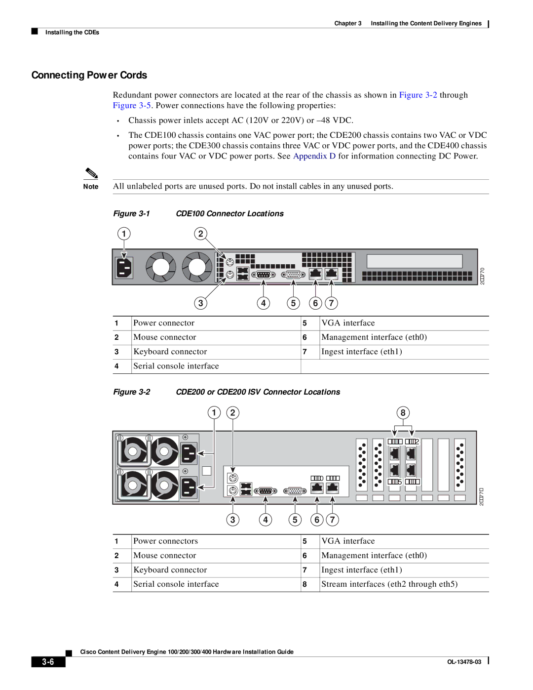
Figure 3-1 CDE100 Connector Locations
12
211770 |
| 3 | 4 | 5 |
| 6 | 7 |
|
|
|
|
|
|
|
1 | Power connector |
|
| 5 |
| VGA interface |
|
|
|
|
|
|
|
2 | Mouse connector |
|
| 6 |
| Management interface (eth0) |
|
|
|
|
|
|
|
3 | Keyboard connector |
|
| 7 |
| Ingest interface (eth1) |
|
|
|
|
|
|
|
4 | Serial console interface |
|
|
|
|
|
|
|
|
|
|
|
|
Figure 3-2 CDE200 or CDE200 ISV Connector Locations
1 | 2 |
|
|
|
| 8 |
|
|
|
|
|
| eth4 eth2 |
|
|
|
| eth0 eth1 | eth5 eth3 | |
|
|
|
|
|
| |
|
|
|
|
|
| 211771 |
| 3 | 4 | 5 | 6 | 7 |
|
1 | Power connectors | 5 | VGA interface |
|
|
|
|
2 | Mouse connector | 6 | Management interface (eth0) |
|
|
|
|
3 | Keyboard connector | 7 | Ingest interface (eth1) |
|
|
|
|
4 | Serial console interface | 8 | Stream interfaces (eth2 through eth5) |
|
|
|
|
Cisco Content Delivery Engine 100/200/300/400 Hardware Installation Guide
|
| |
|