Appendix D Connecting DC Power
Connecting DC Power to a CDE200
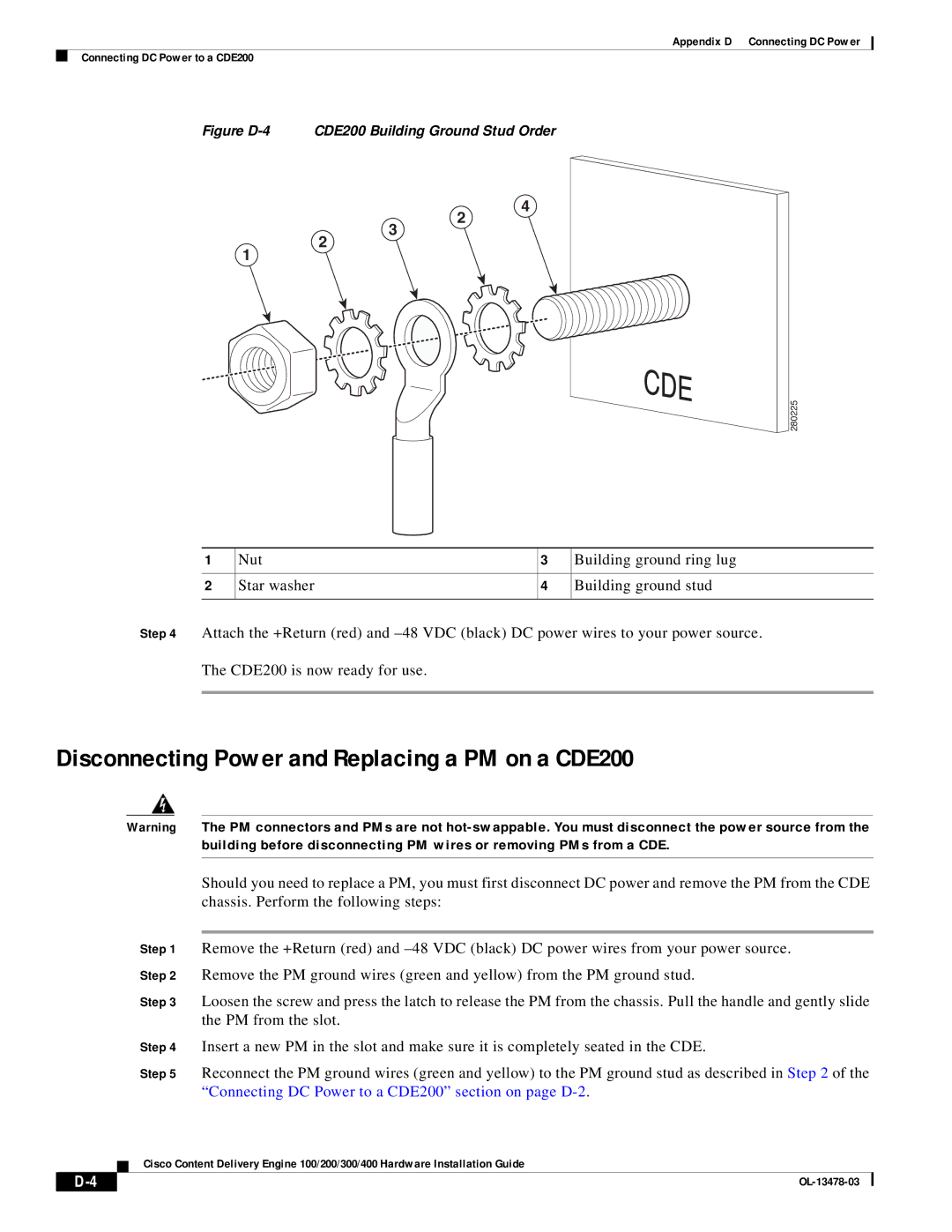
Figure D-4 CDE200 Building Ground Stud Order
4
2
3
2
1
280225
1 | Nut | 3 | Building ground ring lug |
|
|
|
|
2 | Star washer | 4 | Building ground stud |
|
|
|
|
Step 4 Attach the +Return (red) and
The CDE200 is now ready for use.
Disconnecting Power and Replacing a PM on a CDE200
|
| Warning | The PM connectors and PMs are not | ||
|
|
|
| building before disconnecting PM wires or removing PMs from a CDE. | |
|
|
|
|
| |
|
|
|
| Should you need to replace a PM, you must first disconnect DC power and remove the PM from the CDE | |
|
|
|
| chassis. Perform the following steps: | |
|
|
|
|
| |
|
|
| Step 1 | Remove the +Return (red) and | |
|
|
| Step 2 | Remove the PM ground wires (green and yellow) from the PM ground stud. | |
|
|
| Step 3 | Loosen the screw and press the latch to release the PM from the chassis. Pull the handle and gently slide | |
|
|
|
| the PM from the slot. | |
|
|
| Step 4 | Insert a new PM in the slot and make sure it is completely seated in the CDE. | |
|
|
| Step 5 | Reconnect the PM ground wires (green and yellow) to the PM ground stud as described in Step 2 of the | |
|
|
|
| “Connecting DC Power to a CDE200” section on page | |
|
|
| Cisco Content Delivery Engine 100/200/300/400 Hardware Installation Guide | ||
|
|
| |||
|
|
|
|
|
|
|
|
|
|
| |
|
|
|
| ||