Appendix D Connecting DC Power
Connecting DC Power to a CDE400
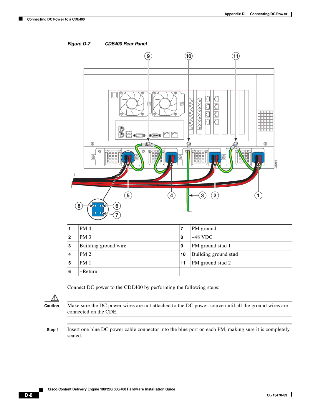
Figure | CDE400 Rear Panel |
|
|
|
|
| 9 |
| 10 |
| 11 |
|
|
|
|
| 280161 |
| 5 | 4 | 3 | 2 | 1 |
8 | 6 |
|
|
|
|
| 7 |
|
|
|
|
1 | PM 4 | 7 | PM ground |
|
|
|
|
2 | PM 3 | 8 |
|
|
|
|
|
3 | Building ground wire | 9 | PM ground stud 1 |
|
|
|
|
4 | PM 2 | 10 | Building ground stud |
|
|
|
|
5 | PM 1 | 11 | PM ground stud 2 |
|
|
|
|
6 | +Return |
|
|
|
|
|
|
Connect DC power to the CDE400 by performing the following steps:
Caution Make sure the DC power wires are not attached to the DC power source until all the ground wires are connected on the CDE.
Step 1 Insert one blue DC power cable connector into the blue port on each PM, making sure it is completely seated.
Cisco Content Delivery Engine 100/200/300/400 Hardware Installation Guide
|
|
| |
|
|