Chapter 2 Replacing Cards in the Cisco 3230 ISR Rugged Enclosure
Card Replacement Process
Reattaching the Wiring Card
The Cisco 3230 Rugged Enclosure supports the version 1 and version 2 of the wiring card.
Attaching Version 1 of the Wiring Card
If you are using version 1 of the wiring card (see Figure
Step 1 Install the wiring card (shown attached to the front of the card stack in Figure
a.Align the wiring card connectors with the headers on the card stack at the front of the extrusion.
b.Secure the wiring card to the extrusion with the eight Phillips
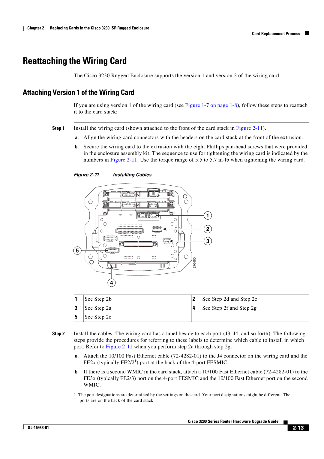
Figure | Installing Cables |
1
2
3
5 |
270460
4
1 | See Step 2b | 2 | See Step 2d and Step 2e |
|
|
|
|
3 | See Step 2a | 4 | See Step 2f and Step 2g |
|
|
|
|
5 | See Step 2c |
|
|
|
|
|
|
Step 2 Install the cables. The wiring card has a label beside to each port (J3, J4, and so forth). The following steps provide the procedures for referring to these labels to determine which cable to install in which port. Refer to Figure
a.Attach the 10/100 Fast Ethernet cable
b.If there is a second WMIC in the card stack, attach a 10/100 Fast Ethernet cable
1.The port designations are determined by the settings on the card. Your port designations might be different. The
ports are on the back of the card stack.
Cisco 3200 Series Router Hardware Upgrade Guide
|
| ||
|
|