Chapter 2 Replacing Cards in the Cisco 3230 ISR Rugged Enclosure
Card Replacement Process
c.If there is a second WMIC in the stack, attach a console cable
d.Route the LED ribbon cable
e.Connect the LED ribbon cable to J5 of the wiring card and to the FESMIC LED header on the card stack at the back of the extrusion.
f.Route the power cable from the I/O end cap under the card stack, toward the back of the extrusion.
g.Connect the power cable to the header on the MRPC.
Attaching the Version 2 of the Wiring Card
If you are using the newer version 2 of the wiring card (see Figure
Step 1 Install the wiring card (shown attached to the front of the card stack in Figure
a.Align the wiring card connectors with the headers on the card stack at the front of the extrusion.
b.Secure the wiring card to the extrusion with the card’s eight Phillips
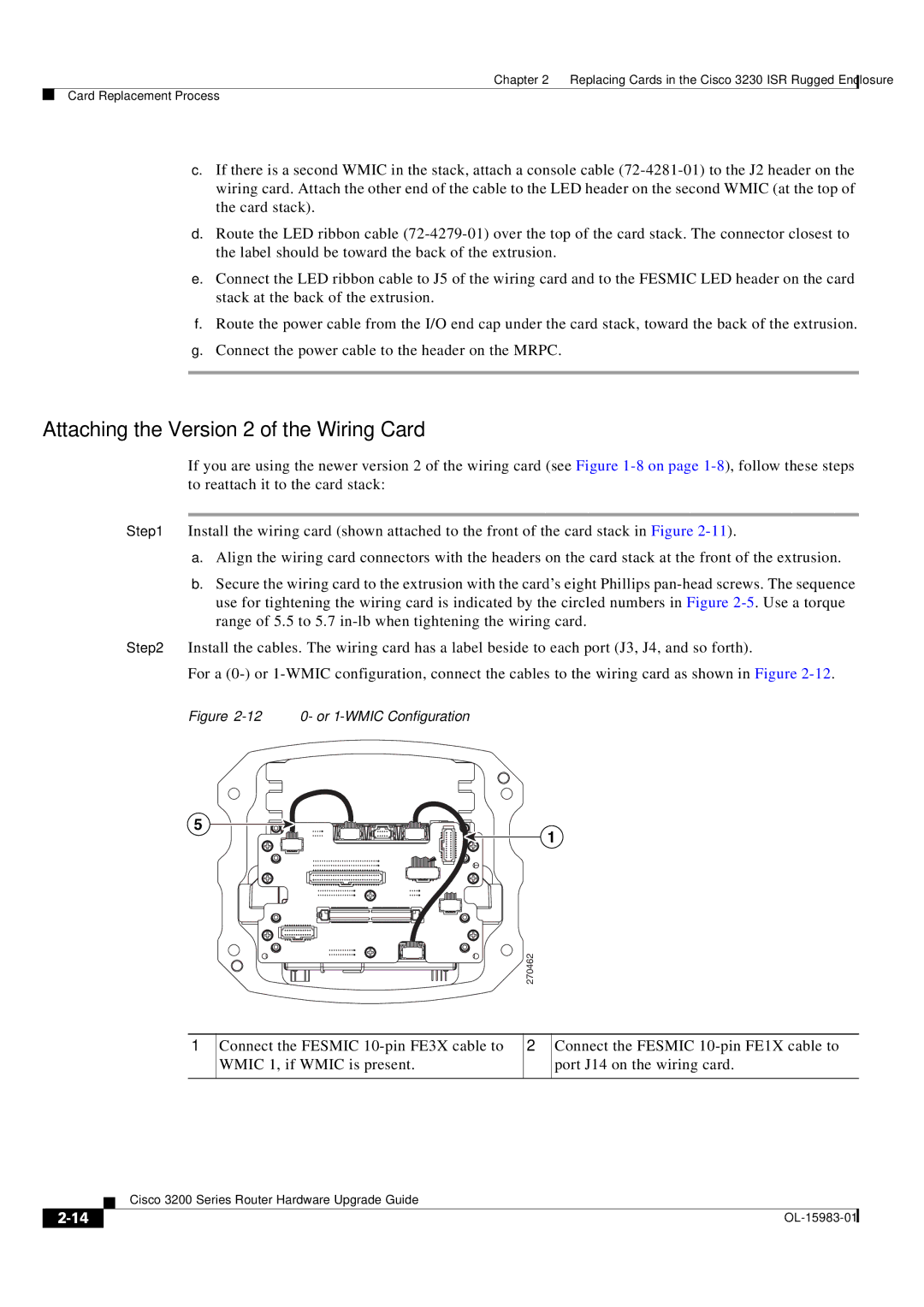
Step 2 Install the cables. The wiring card has a label beside to each port (J3, J4, and so forth).
For a
Figure 2-12 0- or 1-WMIC Configuration
5
1
270462
1
Connect the FESMIC
2
Connect the FESMIC
| Cisco 3200 Series Router Hardware Upgrade Guide |
|