Chapter 3 Replacing Cards in the Cisco ISR 3270 Rugged Enclosure
Card Replacement Process
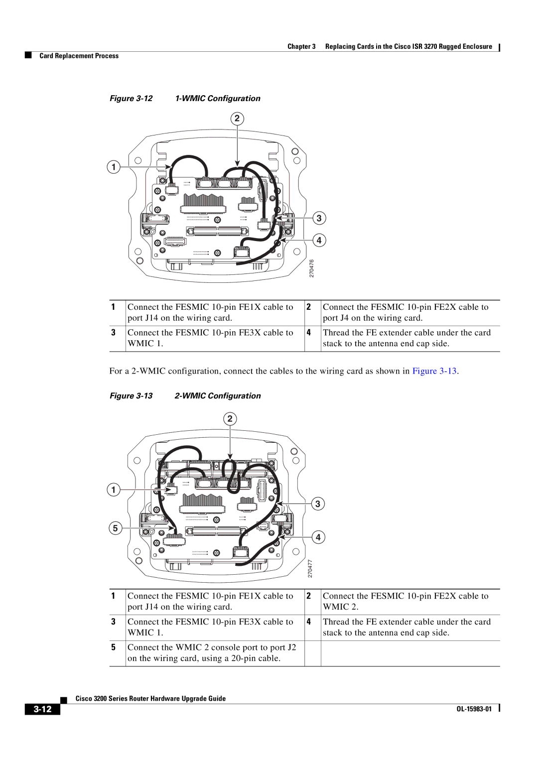
Figure 3-12 1-WMIC Configuration
2
1
|
|
|
|
| 3 | |
|
|
|
|
| ||
|
|
|
|
| 4 | |
|
|
|
| 270476 | ||
|
|
|
|
|
| |
|
|
|
|
| ||
1 | Connect the FESMIC | 2 |
| Connect the FESMIC | ||
| port J14 on the wiring card. |
|
| port J4 on the wiring card. | ||
|
|
|
|
| ||
3 | Connect the FESMIC | 4 |
| Thread the FE extender cable under the card | ||
| WMIC 1. |
|
| stack to the antenna end cap side. | ||
|
|
|
|
|
|
|
For a
Figure 3-13 2-WMIC Configuration
2
1
5 |
|
|
|
|
|
| 3 |
|
| ||||
|
|
|
|
|
|
| |||||||
|
|
|
|
|
| 4 |
|
| |||||
|
|
|
|
|
|
|
| ||||||
|
|
|
|
|
|
|
|
|
|
|
|
| |
|
|
|
|
|
|
|
|
|
| 270477 |
| ||
|
|
|
|
|
|
|
|
|
|
|
|
| |
|
|
|
|
|
|
| |||||||
1 |
| Connect the FESMIC | 2 |
| Connect the FESMIC | ||||||||
|
|
|
|
|
| port J14 on the wiring card. |
|
| WMIC 2. | ||||
|
|
|
|
|
|
| |||||||
3 |
| Connect the FESMIC | 4 |
| Thread the FE extender cable under the card | ||||||||
|
|
|
|
|
| WMIC 1. |
|
| stack to the antenna end cap side. | ||||
|
|
|
|
|
|
|
| ||||||
5 |
| Connect the WMIC 2 console port to port J2 |
|
|
|
| |||||||
|
|
|
|
|
| on the wiring card, using a |
|
|
|
| |||
|
|
|
|
|
|
|
|
|
| ||||
|
|
| Cisco 3200 Series Router Hardware Upgrade Guide |
|
|
|
| ||||||
|
|
|
|
|
|
| |||||||
|
|
|
|
|
|
|
|
|
|
|
|
|
|
|
|
|
|
|
|
|
|
|
|
|
| ||
|
|
|
|
|
|
|
|
|
|
| |||