Chapter 3 Replacing Cards in the Cisco ISR 3270 Rugged Enclosure
Card Replacement Process
Removing the I/O End Cap
To remove the I/O end cap, follow these steps:
Step 1 Use a
Note If a protective end cap cover (see Figure
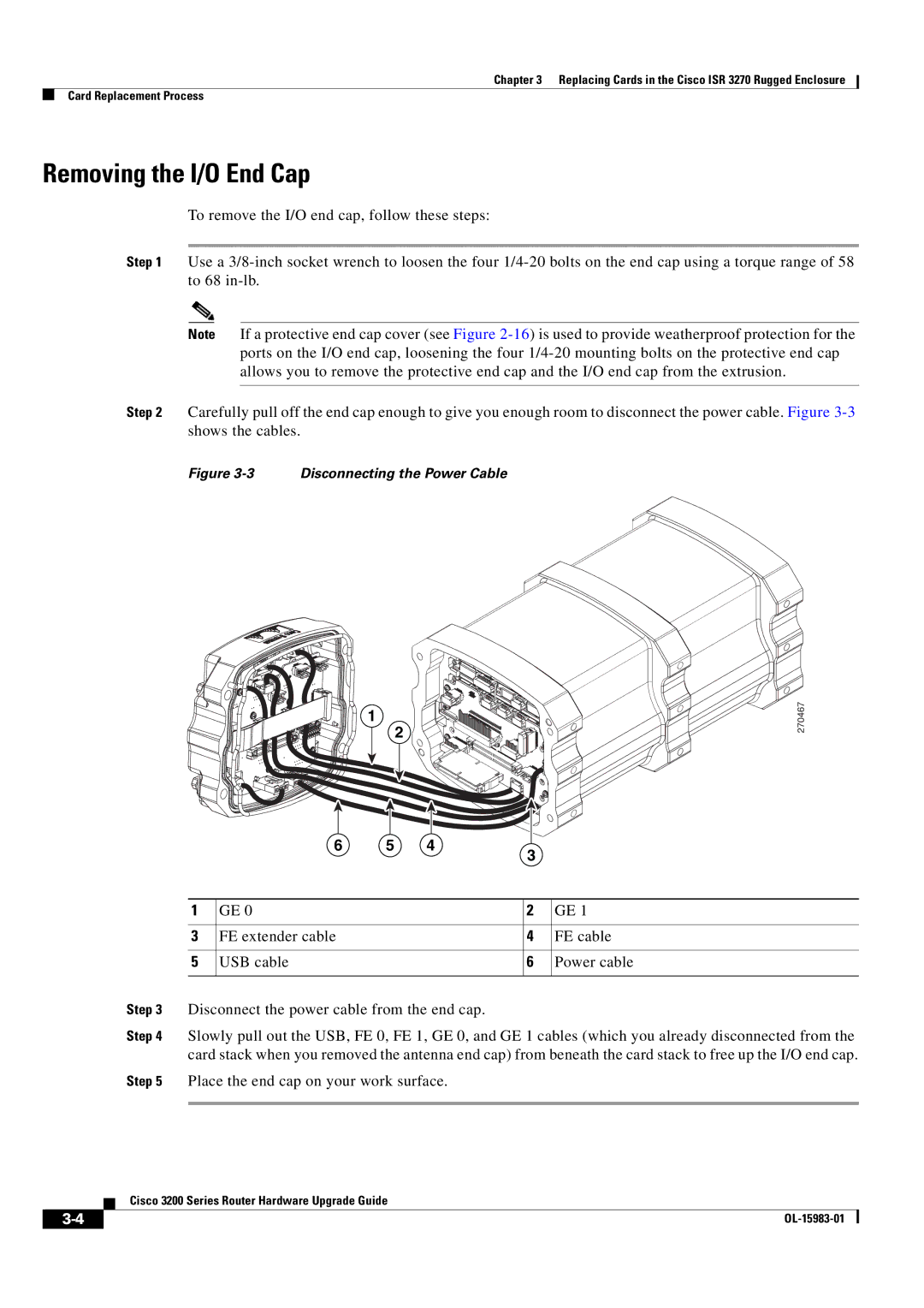
Step 2 Carefully pull off the end cap enough to give you enough room to disconnect the power cable. Figure
Figure 3-3 Disconnecting the Power Cable
1
2
6 5 4
3
270467
| 1 | GE 0 | 2 | GE 1 |
|
|
|
|
|
| 3 | FE extender cable | 4 | FE cable |
|
|
|
|
|
| 5 | USB cable | 6 | Power cable |
|
|
|
|
|
Step 3 | Disconnect the power cable from the end cap. |
|
| |
Step 4 | Slowly pull out the USB, FE 0, FE 1, GE 0, and GE 1 cables (which you already disconnected from the | |||
| card stack when you removed the antenna end cap) from beneath the card stack to free up the I/O end cap. | |||
Step 5 | Place the end cap on your work surface. |
|
| |
|
|
|
|
|
Cisco 3200 Series Router Hardware Upgrade Guide
| ||
|