Chapter 3 Replacing Cards in the Cisco ISR 3270 Rugged Enclosure
Card Replacement Process
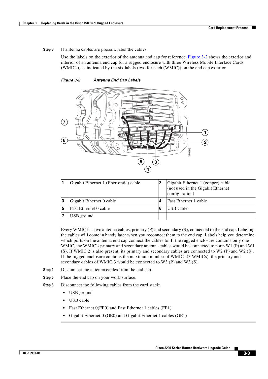
Step 3 If antenna cables are present, label the cables.
Use the labels on the exterior of the antenna end cap for reference. Figure
Figure 3-2 Antenna End Cap Labels
7
|
|
| 1 |
6 |
|
| 2 |
|
|
| |
|
|
| 270466 |
| 5 | 3 |
|
|
| 4 |
|
1 | Gigabit Ethernet 1 | 2 | Gigabit Ethernet 1 (copper) cable |
|
|
| (not used in the Gigabit Ethernet |
|
|
| configuration) |
3 | Gigabit Ethernet 0 cable | 4 | Fast Ethernet 1 cable |
5 | Fast Ethernet 0 cable | 6 | USB cable |
7 | USB ground |
|
|
Every WMIC has two antenna cables, primary (P) and secondary (S), connected to the end cap. Labeling the cables will come in handy later when you reconnect them to the end cap. Labels help you determine which ports on the antenna end cap connect the cables to. If the rugged enclosure contains only one WMIC, the WMIC’s primary and secondary antenna cables would be connected to ports W1 (P) and W1
(S). If WMIC 2 is also present, its primary and secondary cables are connected to W2 (P) and W2 (S). If the rugged enclosure contains the maximum number of WMICs (3 WMICs), the primary and secondary cables of WMIC 3 would be connected to W3 (P) and W3 (S).
Step 4 Disconnect the antenna cables from the end cap.
Step 5 Place the end cap on your work surface.
Step 6 Disconnect the following cables from the card stack:
•USB ground
•USB cable
•Fast Ethernet 0(FE0) and Fast Ethernet 1 cables (FE1)
•Gigabit Ethernet 0 (GE0) and Gigabit Ethernet 1 cables (GE1)
Cisco 3200 Series Router Hardware Upgrade Guide
|
| ||
|
|