Chapter 2 Replacing Cards in the Cisco 3230 ISR Rugged Enclosure
Card Replacement Process
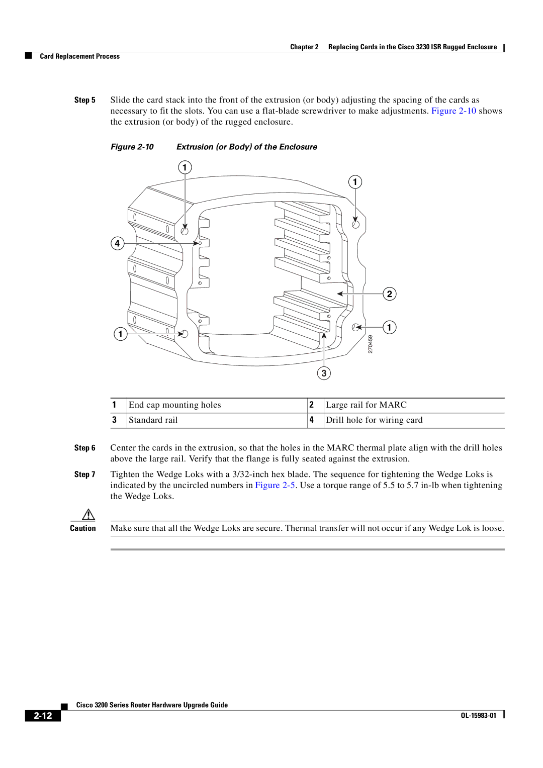
Step 5 Slide the card stack into the front of the extrusion (or body) adjusting the spacing of the cards as necessary to fit the slots. You can use a
Figure 2-10 Extrusion (or Body) of the Enclosure
1
4
1
1
2
1
270459
|
|
| 3 | |
|
|
|
|
|
1 | End cap mounting holes | 2 |
| Large rail for MARC |
|
|
|
|
|
3 | Standard rail | 4 |
| Drill hole for wiring card |
|
|
|
|
|
Step 6 Center the cards in the extrusion, so that the holes in the MARC thermal plate align with the drill holes above the large rail. Verify that the flange is fully seated against the extrusion.
Step 7 Tighten the Wedge Loks with a
Caution Make sure that all the Wedge Loks are secure. Thermal transfer will not occur if any Wedge Lok is loose.
| Cisco 3200 Series Router Hardware Upgrade Guide |
|