Chapter 1 Product Overview
System Architecture
Catalyst 4503 with a single 15A circuit. Likewise, it is possible to deploy a fully populated Cisco Catalyst 4510R with two 20A and one 15A circuits rather than a single 60A connection, which often requires rack rewiring.
Management Flow
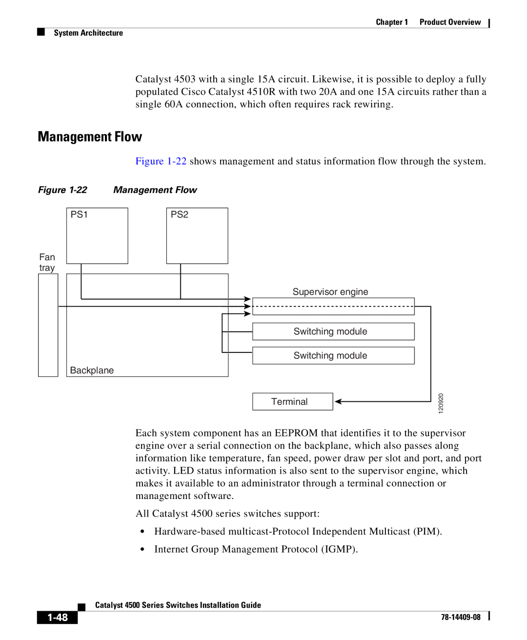
Figure 1-22 shows management and status information flow through the system.
Figure 1-22 Management Flow
PS1 | PS2 |
Fan tray
Backplane
Supervisor engine
Switching module
Switching module
Terminal
120920
Each system component has an EEPROM that identifies it to the supervisor engine over a serial connection on the backplane, which also passes along information like temperature, fan speed, power draw per slot and port, and port activity. LED status information is also sent to the supervisor engine, which makes it available to an administrator through a terminal connection or management software.
All Catalyst 4500 series switches support:
•
•Internet Group Management Protocol (IGMP).
| Catalyst 4500 Series Switches Installation Guide |
|