Chapter 1 Product Overview
System Architecture
System Architecture
This section describes the interaction between the various system components of Catalyst 4500 series switches. A Catalyst 4503 only is shown in the examples.
Power Flow
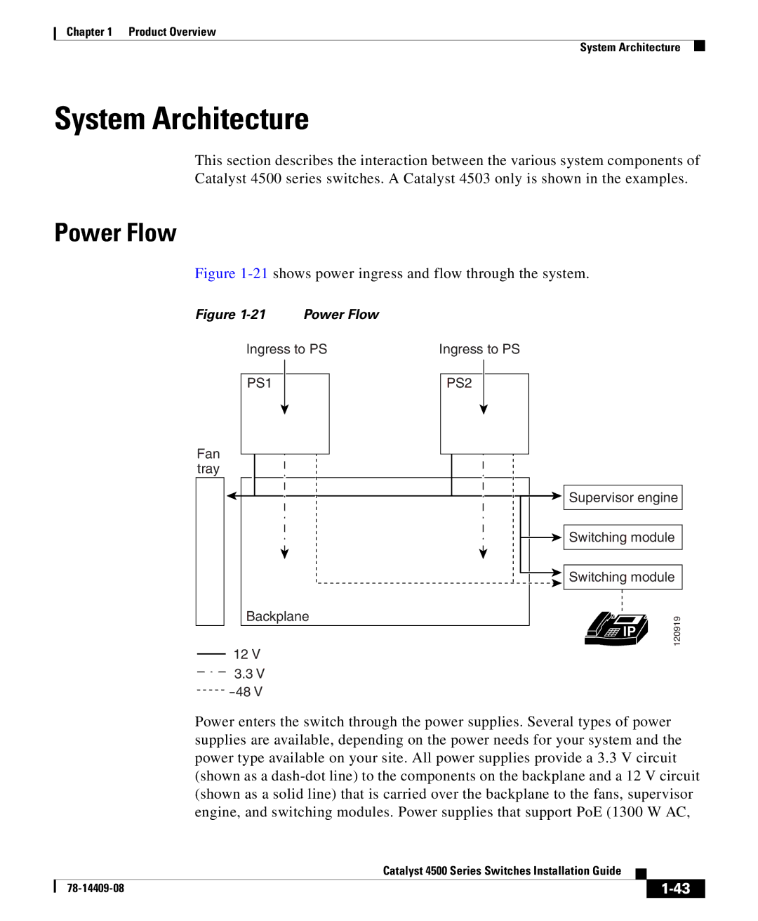
Figure 1-21 shows power ingress and flow through the system.
Figure | Power Flow |
|
Ingress to PS | Ingress to PS | |
PS1 | PS2 |
|
Fan |
|
|
tray |
|
|
| Supervisor engine | |
| Switching module | |
| Switching module | |
Backplane | IP | 120919 |
| ||
12 V |
| |
|
| |
3.3 V |
|
|
48 V |
|
|
Power enters the switch through the power supplies. Several types of power supplies are available, depending on the power needs for your system and the power type available on your site. All power supplies provide a 3.3 V circuit (shown as a
Catalyst 4500 Series Switches Installation Guide
| ||
|