Chapter 3 Installing the Switch in a Rack
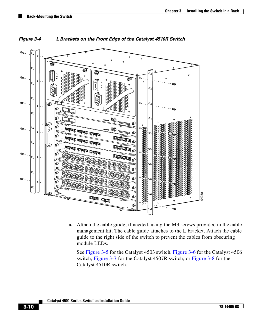
Figure 3-4 L Brackets on the Front Edge of the Catalyst 4510R Switch
UPLINK
UPLINK
STATUS
UPLINK
UPLINK
STATUS
CONSOLE | 10/100 |
|
CONSOLE | 10/100 |
|
| STATUS |
|
|
|
| 1 | 2 |
|
|
|
| 3 | 4 |
|
WS- |
| 5 | 6 | |
|
|
| ||
| STATUS |
|
|
|
| 1 | 2 |
|
|
|
| 3 | 4 |
|
WS- |
| 5 | 6 | |
| STATUS |
|
|
|
| 1 | 2 |
|
|
WS- |
| 3 | 4 |
|
|
| 5 | 6 | |
| STATUS |
|
|
|
WS- |
|
|
| |
|
|
|
| |
| STATUS |
|
|
|
WS- |
|
|
| |
| STATUS |
|
|
|
WS- |
|
|
| |
|
|
|
| |
| STATUS |
|
|
|
7 | 8 |
|
|
| 9 | 10 |
|
|
| 11 | 12 |
|
|
| 17 |
7 | 8 |
|
|
| 9 | 10 |
|
|
| 11 | 12 |
|
|
| 17 |
7 | 8 |
|
|
| 9 | 10 |
|
|
| 11 | 12 |
|
|
| 17 |
1 | 94938 |
2
c.Attach the cable guide, if needed, using the M3 screws provided in the cable management kit. The cable guide attaches to the L bracket. Attach the cable guide to the right side of the switch to prevent the cables from obscuring module LEDs.
See Figure
| Catalyst 4500 Series Switches Installation Guide |
|