Chapter 3 Installing the Switch in a Rack
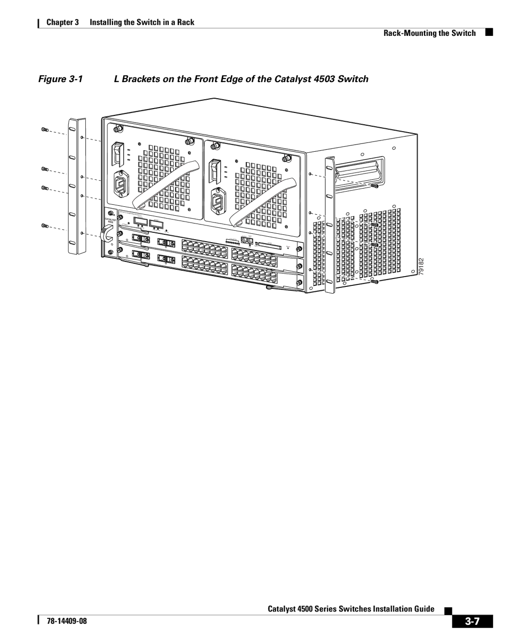
Figure 3-1 L Brackets on the Front Edge of the Catalyst 4503 Switch
4506 |
4503 ![]()
SUPERVISOR | |
| |
| ENGINE IV |
| UPLINK 1 |
| UPLINK 2 |
STATUS | |
| LINE ACTIVE |
| LINE ACTIVE |
| ACTIVE |
1
13
13
CONSOLE | 1M0/1G0T0 |
|
UTILIZATION |
|
|
1% |
|
|
100% | LINK | EJECT |
1 |
| |
13 |
|
|
1 |
|
|
13 |
|
|
FLASH
RESET
79182
|
| Catalyst 4500 Series Switches Installation Guide |
|
|
|
|
| ||
|
|
| ||
|
|
|