Chapter 5 Troubleshooting
Troubleshooting Switching Modules
•The switch powers down and stays down for a few minutes to a few days for no clear reason.
•The
•The Status LEDs on the switching modules and the supervisor engine are flashing green.
•CPU Utilization LEDs are flashing green or off.
If you observe these conditions, contact the Cisco TAC for assistance in ordering replacement redundancy modules and a clock.
Troubleshooting Switching Modules
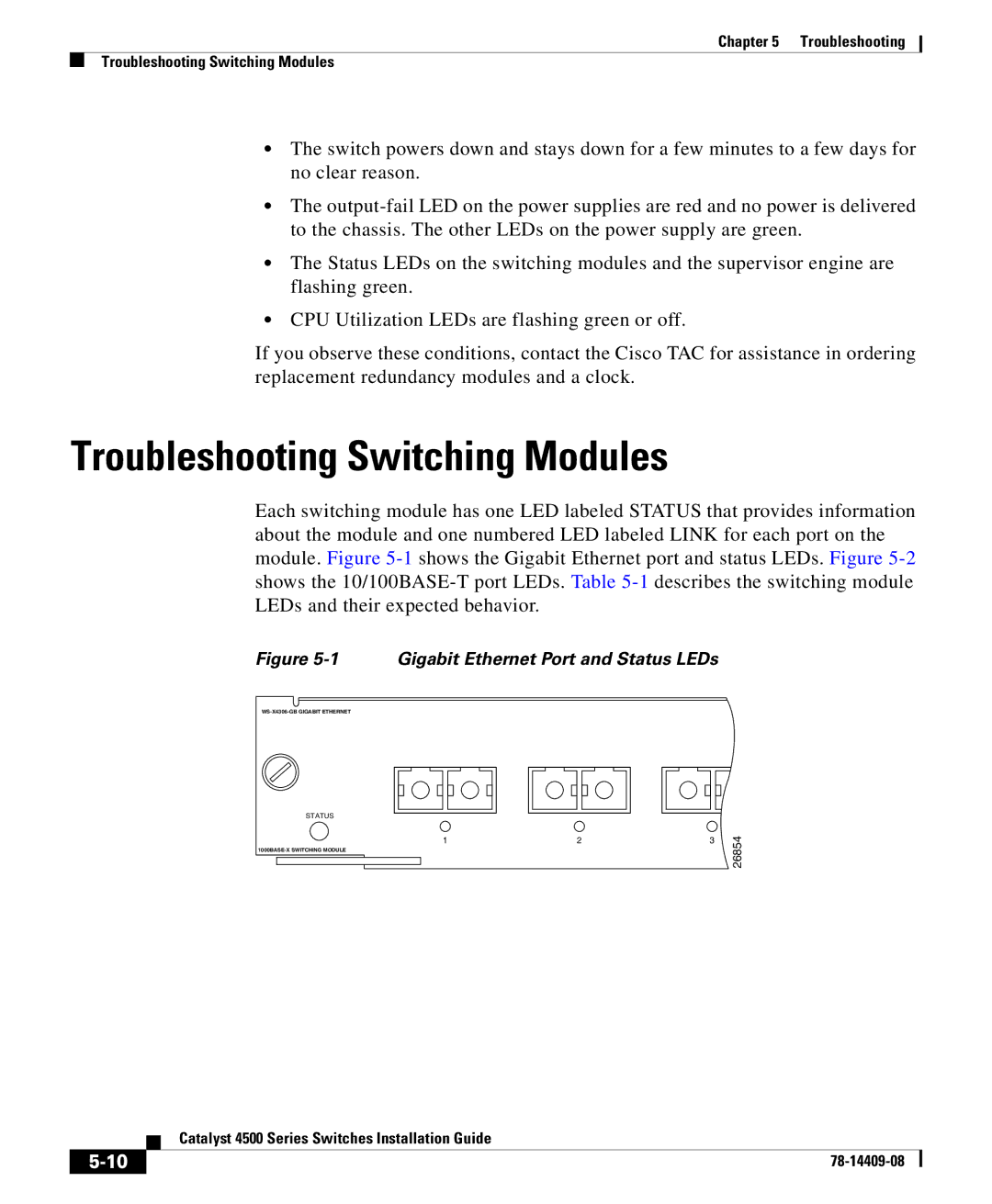
Each switching module has one LED labeled STATUS that provides information about the module and one numbered LED labeled LINK for each port on the module. Figure
Figure 5-1 Gigabit Ethernet Port and Status LEDs
STATUS
1 | 2 |
3
26854
| Catalyst 4500 Series Switches Installation Guide |
|