Overview
Table 1 Content Switching Module Features (continued)
Feature
Description
Health Monitoring | TCP, HTTP, ICMP, Telnet, FTP |
|
|
Other Features | SSL session ID, cookie and source IP |
| connections |
| Fragmented IP frames support |
| MTU2 of 9000 |
| Load and availability reporting supporting remote monitoring and |
| management |
| High availability preventing service disruptions |
| Redundant modules configured for |
|
|
1.SSL = Secure Socket Layer
2.MTU = Maximum Transmission Unit
Front Panel Description
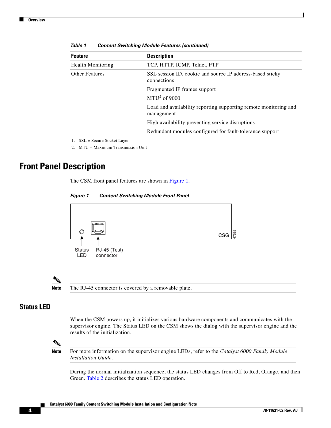
The CSM front panel features are shown in Figure 1.
Figure 1 Content Switching Module Front Panel
CSG
47525
Status | |
LED | connector |
Note The
Status LED
When the CSM powers up, it initializes various hardware components and communicates with the supervisor engine. The Status LED on the CSM shows the dialog with the supervisor engine and the results of the initialization.
Note For more information on the supervisor engine LEDs, refer to the Catalyst 6000 Family Module Installation Guide.
During the normal initialization sequence, the status LED changes from Off to Red, Orange, and then Green. Table 2 describes the status LED operation.
| Catalyst 6000 Family Content Switching Module Installation and Configuration Note |
4 |