Verifying the Installation
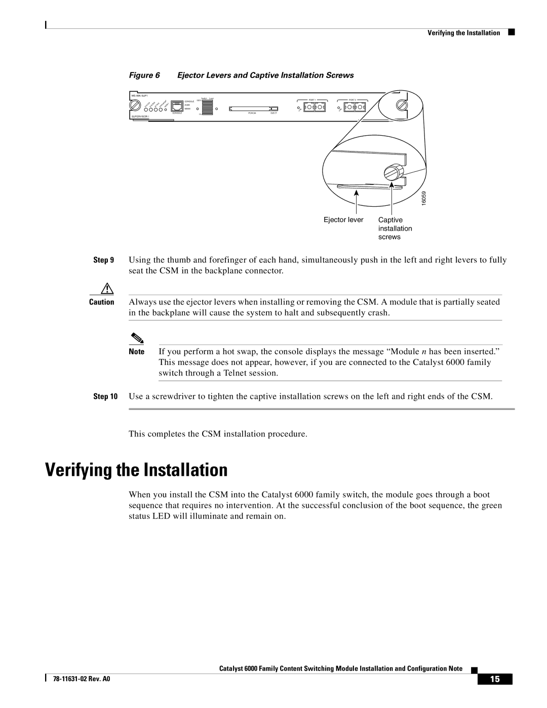
Figure 6 Ejector Levers and Captive Installation Screws
STATUS SYSTEMACTIVE MGMT
PWR RESET
SUPERVISOR I
| Switch | Load |
|
CONSOLE | 100% |
|
|
|
|
| |
PORT |
|
|
|
MODE |
|
|
|
CONSOLE | 1% | PCMCIA | EJECT |
|
|
|
PORT 1
LINK
PORT 2
LINK
16059
Ejector lever | Captive |
| installation |
| screws |
Step 9 Using the thumb and forefinger of each hand, simultaneously push in the left and right levers to fully seat the CSM in the backplane connector.
Caution Always use the ejector levers when installing or removing the CSM. A module that is partially seated in the backplane will cause the system to halt and subsequently crash.
Note If you perform a hot swap, the console displays the message “Module n has been inserted.” This message does not appear, however, if you are connected to the Catalyst 6000 family switch through a Telnet session.
Step 10 Use a screwdriver to tighten the captive installation screws on the left and right ends of the CSM.
This completes the CSM installation procedure.
Verifying the Installation
When you install the CSM into the Catalyst 6000 family switch, the module goes through a boot sequence that requires no intervention. At the successful conclusion of the boot sequence, the green status LED will illuminate and remain on.
|
| Catalyst 6000 Family Content Switching Module Installation and Configuration Note |
|
|
|
|
|
| |||
|
|
| 15 |
| |
|
|
|
|