Installing the Content Switching Module
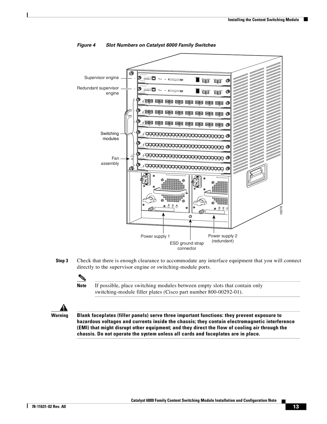
Figure 4 Slot Numbers on Catalyst 6000 Family Switches
Supervisor engine  1
1
Redundant supervisor  2 engine
3
4
5
Switching ![]() 6
6 ![]() modules
modules
7
8
Fan | FAN |
STATUS | |
| |
assembly |
|
9
|
|
|
|
|
|
|
|
|
|
|
|
|
|
|
|
|
|
|
|
|
|
| |
|
|
|
| CONSOLE |
|
|
|
|
|
|
|
|
|
| 100%Switch | Load |
|
|
|
|
|
|
|
|
|
|
|
|
|
|
|
|
|
|
|
|
|
|
|
| PORT 1 |
|
|
|
|
| |
|
|
|
| PORT |
|
|
|
|
|
|
|
|
|
|
|
|
|
|
|
| PORT 2 |
| |
|
|
|
| MODE |
|
|
|
|
|
|
|
|
|
|
|
|
|
|
|
|
|
| |
SUPERVISOR2 |
| CONSOLE |
|
|
|
|
|
| PCMCIA |
|
|
|
|
|
|
|
|
|
|
|
|
|
|
|
|
|
|
|
|
|
|
| EJECT |
|
|
| 1% |
|
|
|
|
|
|
|
| ||
|
|
|
|
|
|
|
|
|
|
|
|
|
|
|
|
|
|
|
|
|
|
| |
|
|
|
|
|
|
|
|
|
|
|
|
|
|
|
|
|
|
|
|
|
|
| |
|
|
|
| CONSOLE |
|
|
|
|
|
|
|
|
|
| 100%Switch | Load |
|
|
|
|
|
|
|
|
|
|
|
|
|
|
|
|
|
|
|
|
|
|
|
| PORT 1 |
|
|
|
|
| |
|
|
|
| PORT |
|
|
|
|
|
|
|
|
|
|
|
|
|
|
|
| PORT 2 |
| |
|
|
|
| MODE |
|
|
|
|
|
|
|
|
|
|
|
|
|
|
|
|
|
| |
SUPERVISOR2 |
| CONSOLE |
|
|
|
|
|
| PCMCIA |
|
|
|
|
|
|
|
|
|
|
|
|
|
|
|
|
|
|
|
|
|
|
| EJECT |
|
|
| 1% |
|
|
|
|
|
|
|
| ||
|
|
|
|
|
|
|
|
|
|
|
|
|
|
|
|
|
|
|
|
|
|
| |
|
|
|
|
|
|
|
|
|
|
|
|
|
|
|
|
|
|
|
|
|
|
| |
| 1 |
|
| 2 |
|
| 3 |
|
| 4 |
|
|
|
|
|
|
|
|
|
|
|
|
|
|
|
|
|
|
|
|
|
|
|
| 5 |
|
| 6 |
|
|
|
|
|
|
| ||
|
|
|
|
|
|
|
|
|
|
|
|
|
|
|
|
|
|
| 7 |
|
| 8 |
|
8 PORT GIGABIT ETHERNET |
|
|
|
|
|
|
|
|
|
|
|
|
|
|
|
|
|
|
|
|
|
|
|
|
|
|
|
|
|
|
|
|
|
|
|
|
|
|
|
|
|
|
|
|
|
| |
| 1 |
|
| 2 |
|
| 3 |
|
| 4 |
|
|
|
|
|
|
|
|
|
|
|
|
|
|
|
|
|
|
|
|
|
|
|
| 5 |
|
| 6 |
|
|
|
|
|
|
| ||
|
|
|
|
|
|
|
|
|
|
|
|
|
|
|
|
|
|
| 7 |
|
| 8 |
|
8 PORT GIGABIT ETHERNET |
|
|
|
|
|
|
|
|
|
|
|
|
|
|
|
|
|
|
|
|
|
|
|
|
|
|
|
|
|
|
|
|
|
|
|
|
|
|
|
|
|
|
|
|
|
| |
| 1 |
|
| 2 |
|
| 3 |
|
| 4 |
|
|
|
|
|
|
|
|
|
|
|
|
|
|
|
|
|
|
|
|
|
|
|
| 5 |
|
| 6 |
|
|
|
|
|
|
| ||
|
|
|
|
|
|
|
|
|
|
|
|
|
|
|
|
|
|
| 7 |
|
| 8 |
|
8 PORT GIGABIT ETHERNET |
|
|
|
|
|
|
|
|
|
|
|
|
|
|
|
|
|
|
|
|
|
|
|
|
|
|
|
|
|
|
|
|
|
|
|
|
|
|
|
|
|
|
|
|
|
| |
1 | 2 | 3 | 4 | 5 | 6 | 7 | 8 | 9 | 10 | 11 | 12 | 13 | 14 | 15 | 16 | 17 | 18 | 19 | 20 | 21 | 22 | 23 | 24 |
24 PORT 100FX |
|
|
|
|
|
|
|
|
|
|
|
|
|
|
|
|
|
|
|
|
|
|
|
|
|
|
|
|
|
|
|
|
|
|
|
|
|
|
|
|
|
|
|
|
|
| |
1 | 2 | 3 | 4 | 5 | 6 | 7 | 8 | 9 | 10 | 11 | 12 | 13 | 14 | 15 | 16 | 17 | 18 | 19 | 20 | 21 | 22 | 23 | 24 |
24 PORT 100FX |
|
|
|
|
|
|
|
|
|
|
|
|
|
|
|
|
|
|
|
|
|
|
|
|
|
|
|
|
|
|
|
|
|
|
|
|
|
|
|
|
|
|
|
|
|
| |
1 | 2 | 3 | 4 | 5 | 6 | 7 | 8 | 9 |
|
|
|
|
|
|
|
|
|
|
|
|
|
|
|
|
|
|
|
|
|
|
| 10 | 11 | 12 | 13 | 14 | 15 | 16 | 17 |
|
|
|
|
|
|
| |
|
|
|
|
|
|
|
|
|
|
|
|
|
|
|
| 18 | 19 | 20 | 21 | 22 | 23 | 24 | |
24 PORT 100FX |
|
|
|
|
|
|
|
|
|
|
|
|
|
|
|
|
|
|
|
|
|
|
|
|
|
|
|
|
|
|
|
|
|
|
|
|
|
|
|
|
|
|
|
|
|
| |
1 | 2 | 3 | 4 | 5 | 6 | 7 | 8 |
|
|
|
|
|
|
|
|
|
|
|
|
|
|
|
|
|
|
|
| 9 | 10 | 11 | 12 | 13 |
|
|
|
|
|
|
|
|
|
|
| ||||
|
|
|
|
|
|
|
|
|
|
|
| 14 | 15 | 16 | 17 | 18 | 19 | 20 | 21 |
|
|
| |
|
|
|
|
|
|
|
|
|
|
|
|
|
|
|
|
|
|
|
| 22 | 23 | 24 | |
24 PORT 100FX |
|
|
|
|
|
|
|
|
|
|
|
|
|
|
|
|
|
|
|
|
|
|
|
o
o![]()
INPUT | FAN OUTPUT |
OK | FAIL |
INPUT | FAN OUTPUT |
OK | FAIL |
16076
Power supply 1 | Power supply 2 |
ESD ground strap
connector
(redundant)
Step 3 Check that there is enough clearance to accommodate any interface equipment that you will connect directly to the supervisor engine or
Note If possible, place switching modules between empty slots that contain only
Warning Blank faceplates (filler panels) serve three important functions: they prevent exposure to hazardous voltages and currents inside the chassis; they contain electromagnetic interference (EMI) that might disrupt other equipment; and they direct the flow of cooling air through the chassis. Do not operate the system unless all cards and faceplates are in place.
|
| Catalyst 6000 Family Content Switching Module Installation and Configuration Note |
|
|
|
|
|
| |||
|
|
| 13 |
| |
|
|
|
|