Configuration Examples
Secure (Router) Mode Configuration
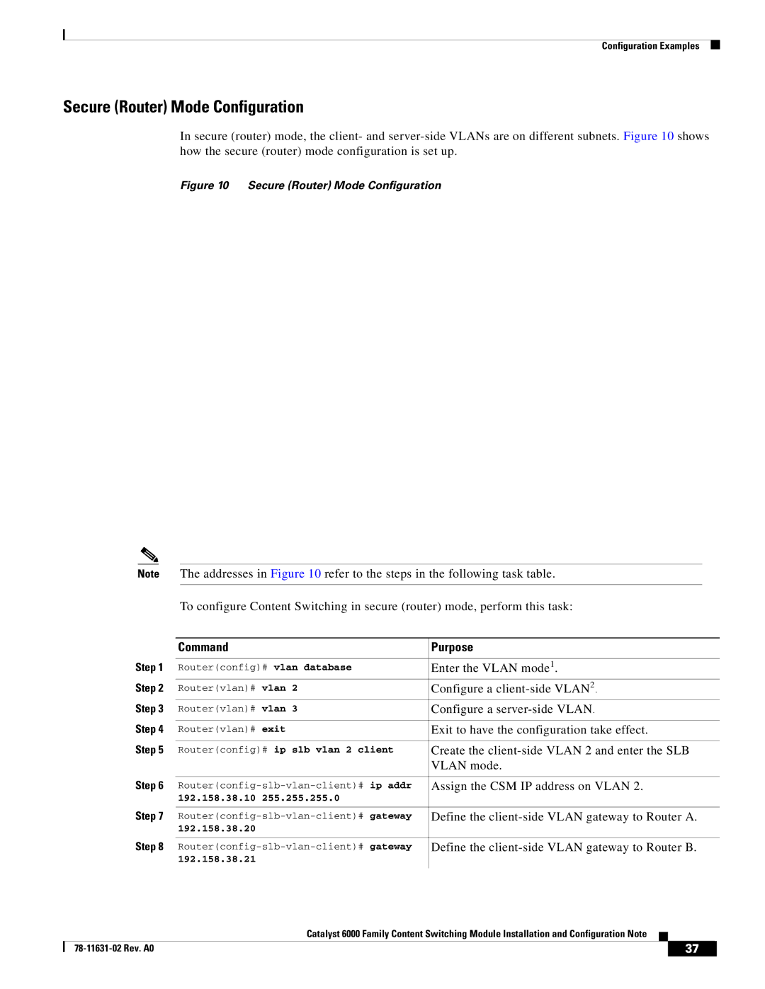
In secure (router) mode, the client- and
Figure 10 Secure (Router) Mode Configuration
Note The addresses in Figure 10 refer to the steps in the following task table.
To configure Content Switching in secure (router) mode, perform this task:
| Command |
| Purpose |
|
|
| |
Step 1 | Router(config)# vlan database | Enter the VLAN mode1. | |
Step 2 | Router(vlan)# vlan 2 | Configure a | |
Step 3 | Router(vlan)# vlan 3 | Configure a | |
Step 4 |
|
| |
Router(vlan)# exit | Exit to have the configuration take effect. | ||
Step 5 |
|
| |
Router(config)# ip slb vlan 2 client | Create the | ||
|
|
| VLAN mode. |
Step 6 |
|
| |
Assign the CSM IP address on VLAN 2. | |||
| 192.158.38.10 | 255.255.255.0 |
|
Step 7 |
|
| |
Define the | |||
| 192.158.38.20 |
|
|
Step 8 |
|
| |
Define the | |||
| 192.158.38.21 |
|
|
|
|
|
|
|
| Catalyst 6000 Family Content Switching Module Installation and Configuration Note |
|
|
|
|
|
| |||
|
|
| 37 |
| |
|
|
|
|