Configuration Examples
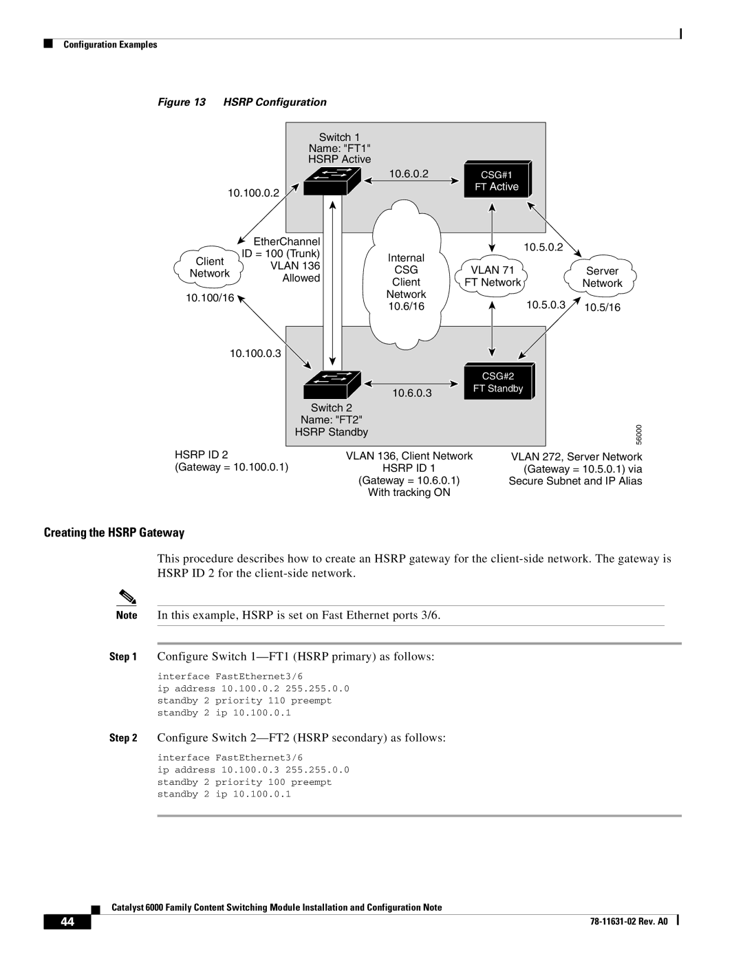
Figure 13 HSRP Configuration
Switch 1 |
|
Name: "FT1" |
|
HSRP Active |
|
10.6.0.2 | CSG#1 |
10.100.0.2 | FT Active |
|
| EtherChannel |
| 10.5.0.2 |
| |
| ID = 100 (Trunk) | Internal |
| ||
Client |
|
| |||
VLAN 136 |
|
| |||
CSG | VLAN 71 | Server | |||
Network | |||||
Allowed | |||||
| Client | FT Network | Network | ||
|
| ||||
10.100/16 |
| Network | 10.5.0.3 |
| |
| 10.6/16 | 10.5/16 | |||
|
|
10.100.0.3 |
|
|
|
| CSG#2 |
| 10.6.0.3 | FT Standby |
|
| |
Switch 2 |
|
|
Name: "FT2" |
| 56000 |
HSRP Standby |
| |
|
|
HSRP ID 2 | VLAN 136, Client Network | VLAN 272, Server Network |
(Gateway = 10.100.0.1) | HSRP ID 1 | (Gateway = 10.5.0.1) via |
| (Gateway = 10.6.0.1) | Secure Subnet and IP Alias |
| With tracking ON |
|
Creating the HSRP Gateway
This procedure describes how to create an HSRP gateway for the
Note In this example, HSRP is set on Fast Ethernet ports 3/6.
Step 1 Configure Switch
interface FastEthernet3/6
ip address 10.100.0.2 255.255.0.0 standby 2 priority 110 preempt standby 2 ip 10.100.0.1
Step 2 Configure Switch 2—FT2 (HSRP secondary) as follows:
interface FastEthernet3/6
ip address 10.100.0.3 255.255.0.0 standby 2 priority 100 preempt standby 2 ip 10.100.0.1
Catalyst 6000 Family Content Switching Module Installation and Configuration Note
44 |
| |
|