Overview
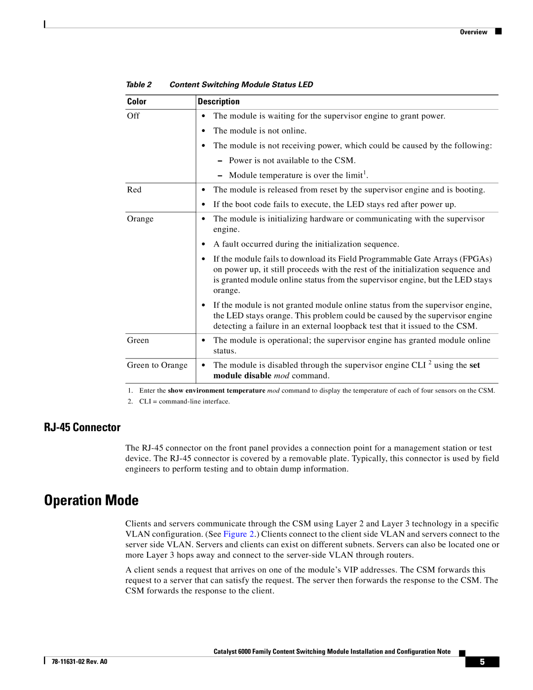
Table 2 Content Switching Module Status LED
Color
Off
Red
Orange
Green
Green to Orange
Description
•The module is waiting for the supervisor engine to grant power.
•The module is not online.
•The module is not receiving power, which could be caused by the following:
–Power is not available to the CSM.
–Module temperature is over the limit1.
•The module is released from reset by the supervisor engine and is booting.
•If the boot code fails to execute, the LED stays red after power up.
•The module is initializing hardware or communicating with the supervisor engine.
•A fault occurred during the initialization sequence.
•If the module fails to download its Field Programmable Gate Arrays (FPGAs) on power up, it still proceeds with the rest of the initialization sequence and is granted module online status from the supervisor engine, but the LED stays orange.
•If the module is not granted module online status from the supervisor engine, the LED stays orange. This problem could be caused by the supervisor engine detecting a failure in an external loopback test that it issued to the CSM.
•The module is operational; the supervisor engine has granted module online status.
•The module is disabled through the supervisor engine CLI 2 using the set module disable mod command.
1.Enter the show environment temperature mod command to display the temperature of each of four sensors on the CSM.
2.CLI =
RJ-45 Connector
The
Operation Mode
Clients and servers communicate through the CSM using Layer 2 and Layer 3 technology in a specific VLAN configuration. (See Figure 2.) Clients connect to the client side VLAN and servers connect to the server side VLAN. Servers and clients can exist on different subnets. Servers can also be located one or more Layer 3 hops away and connect to the
A client sends a request that arrives on one of the module’s VIP addresses. The CSM forwards this request to a server that can satisfy the request. The server then forwards the response to the CSM. The CSM forwards the response to the client.
|
| Catalyst 6000 Family Content Switching Module Installation and Configuration Note |
|
|
|
|
|
| |||
|
|
| 5 |
| |
|
|
|
|
