Configuration Examples
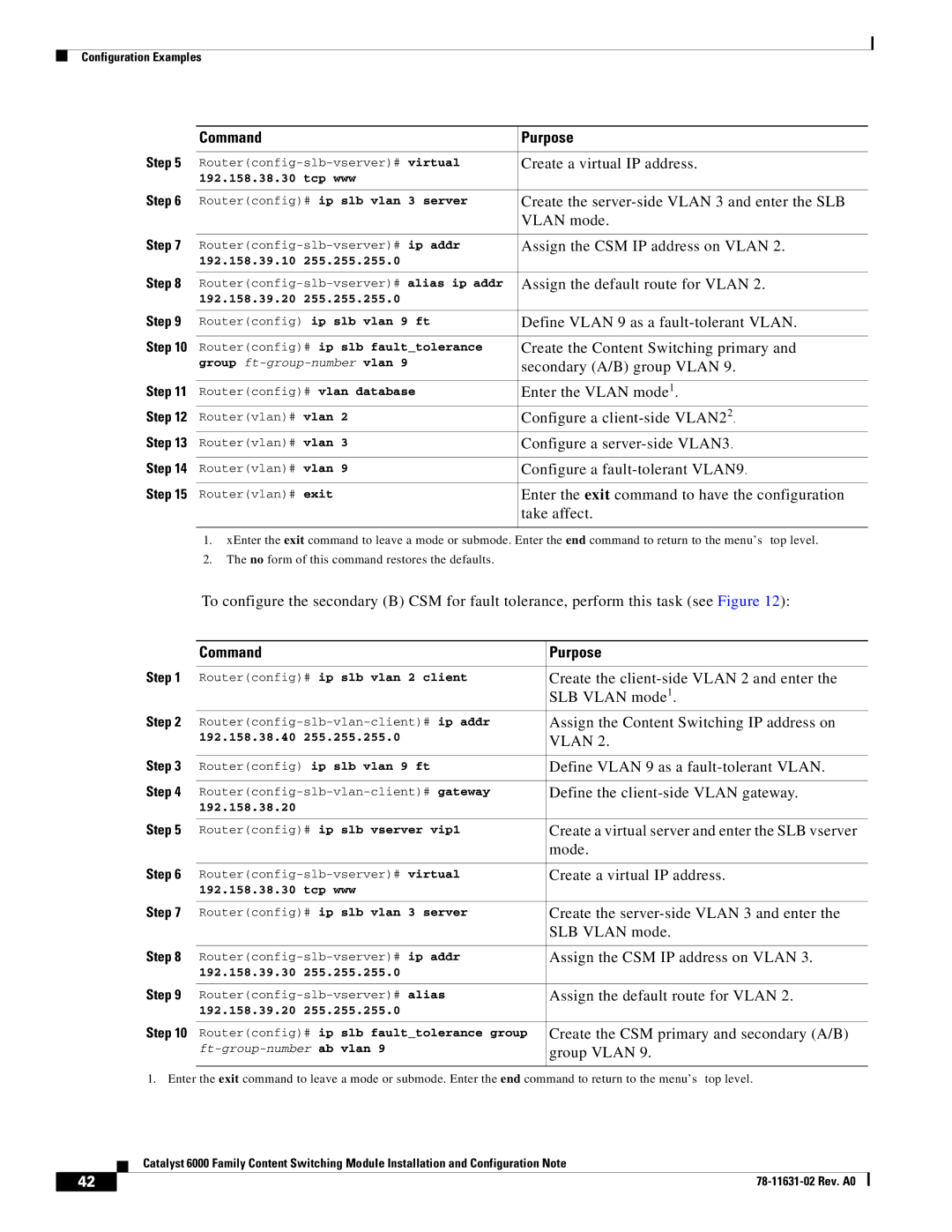
| Command |
| Purpose |
Step 5 |
|
| |
Create a virtual IP address. | |||
| 192.158.38.30 tcp www |
| |
Step 6 |
|
| |
Router(config)# ip slb vlan 3 server | Create the | ||
|
|
| VLAN mode. |
Step 7 |
|
| |
Assign the CSM IP address on VLAN 2. | |||
| 192.158.39.10 | 255.255.255.0 |
|
Step 8 |
|
| |
Assign the default route for VLAN 2. | |||
| 192.158.39.20 | 255.255.255.0 |
|
Step 9 |
|
| |
Router(config) ip slb vlan 9 ft | Define VLAN 9 as a | ||
Step 10 |
|
| |
Router(config)# ip slb fault_tolerance | Create the Content Switching primary and | ||
| group | secondary (A/B) group VLAN 9. | |
|
|
| |
Step 11 | Router(config)# vlan database | Enter the VLAN mode1. | |
Step 12 | Router(vlan)# vlan 2 | Configure a | |
Step 13 | Router(vlan)# vlan 3 | Configure a | |
|
|
| |
Step 14 | Router(vlan)# vlan 9 | Configure a | |
Step 15 |
|
| |
Router(vlan)# exit | Enter the exit command to have the configuration | ||
|
|
| take affect. |
|
|
|
|
1.xEnter the exit command to leave a mode or submode. Enter the end command to return to the menu’s top level.
2.The no form of this command restores the defaults.
To configure the secondary (B) CSM for fault tolerance, perform this task (see Figure 12):
| Command |
| Purpose |
Step 1 |
|
| |
Router(config)# ip slb vlan 2 client | Create the | ||
|
|
| SLB VLAN mode1. |
Step 2 | Assign the Content Switching IP address on | ||
| 192.158.38.40 255.255.255.0 | VLAN 2. | |
Step 3 |
|
| |
Router(config) ip slb vlan 9 ft | Define VLAN 9 as a | ||
Step 4 |
|
| |
Define the | |||
| 192.158.38.20 |
|
|
Step 5 |
|
| |
Router(config)# ip slb vserver vip1 | Create a virtual server and enter the SLB vserver | ||
|
|
| mode. |
Step 6 |
|
| |
Create a virtual IP address. | |||
| 192.158.38.30 tcp www |
| |
Step 7 |
|
| |
Router(config)# ip slb vlan 3 server | Create the | ||
|
|
| SLB VLAN mode. |
Step 8 |
|
| |
Assign the CSM IP address on VLAN 3. | |||
| 192.158.39.30 | 255.255.255.0 |
|
Step 9 |
|
| |
Assign the default route for VLAN 2. | |||
| 192.158.39.20 | 255.255.255.0 |
|
Step 10 |
|
| |
Router(config)# ip slb fault_tolerance group | Create the CSM primary and secondary (A/B) | ||
| group VLAN 9. | ||
|
|
|
|
1. Enter the exit command to leave a mode or submode. Enter the end command to return to the menu’s top level.
| Catalyst 6000 Family Content Switching Module Installation and Configuration Note |
42 |