Chapter 4 Configuring Interfaces
Configuring 802.1Q VLAN Encapsulation
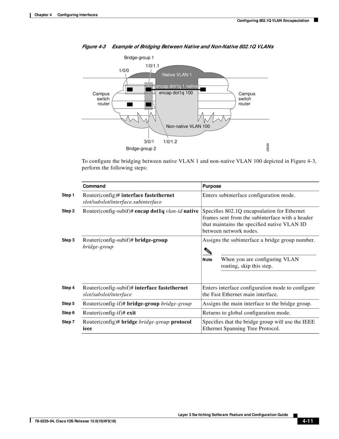
Figure 4-3 Example of Bridging Between Native and Non-Native 802.1Q VLANs
1/0/1.1
| 1/0/0 |
|
|
| Native VLAN 1 |
|
| ||
|
|
|
|
|
|
|
|
| |
|
|
|
|
|
|
| encap dot1q 1 native |
|
|
|
|
|
|
|
|
|
|
| |
Campus |
|
|
|
|
|
| encap dot1q 100 |
| Campus |
|
|
|
|
|
|
| |||
|
|
|
|
|
| ||||
switch |
|
|
|
|
|
|
|
| switch |
router |
|
|
|
|
|
|
|
| router |
|
|
|
|
|
|
|
| ||
3/0/1 1/0/1.2
28089
To configure the bridging between native VLAN 1 and
| Command | Purpose |
| |||
Step 1 |
|
|
| |||
Router(config)# interface fastethernet | Enters subinterface configuration mode. |
| ||||
| slot/subslot/interface.subinterface |
|
|
|
|
|
Step 2 |
|
|
| |||
Specifies 802.1Q encapsulation for Ethernet |
| |||||
|
| frames sent from the subinterface with a header |
| |||
|
| that maintains the specified native VLAN ID |
| |||
|
| between network nodes. |
| |||
Step 3 |
|
|
| |||
Assigns the subinterface a bridge group number. |
| |||||
|
|
|
|
|
|
|
|
|
|
|
|
|
|
|
| Note | When you are configuring VLAN |
| ||
|
|
|
|
| routing, skip this step. |
|
Step 4 |
|
|
|
| ||
|
|
| ||||
Enters interface configuration mode to configure |
| |||||
| slot/subslot/interface | the Fast Ethernet main interface. |
| |||
Step 5 |
|
|
| |||
Assigns the main interface to the bridge group. |
| |||||
Step 6 |
|
|
| |||
Returns to global configuration mode. |
| |||||
Step 7 |
|
|
| |||
Router(config)# bridge | Specifies that the bridge group will use the IEEE |
| ||||
| ieee | Ethernet Spanning Tree Protocol. |
| |||
|
|
|
|
|
|
|
|
| Layer 3 Switching Software Feature and Configuration Guide |
|
|
|
|
|
| |||
|
|
|
| ||
|
|
|
|