Chapter 4 Configuring Interfaces
About ATM Uplinks (Catalyst 8540)
SR1 | 72036 | SR2 | 18806 | SR3 | 0 | SR4 | 0 | SR5 | 0 |
MT1 | 15143 | MT2 | 0 | MT3 | 0 | MT4 | 0 | MT5 | 6 |
MT6 | 0 | MT7 | 0 | MT8 | 0 | MT9 | 0 |
|
|
ST1 | 0 | ST2 | 0 |
|
|
|
|
|
|
MRXS | 262160 | MTXS | 16 | SRXS 3 | STXS 0 |
|
| ||
About ATM Uplinks (Catalyst 8540)
ATM uses
For further information about ATM and its implementation on the Catalyst 8540 MSR and
Catalyst 8510 MSR, refer to the Guide to ATM Technology.
About the ATM Uplink Interface
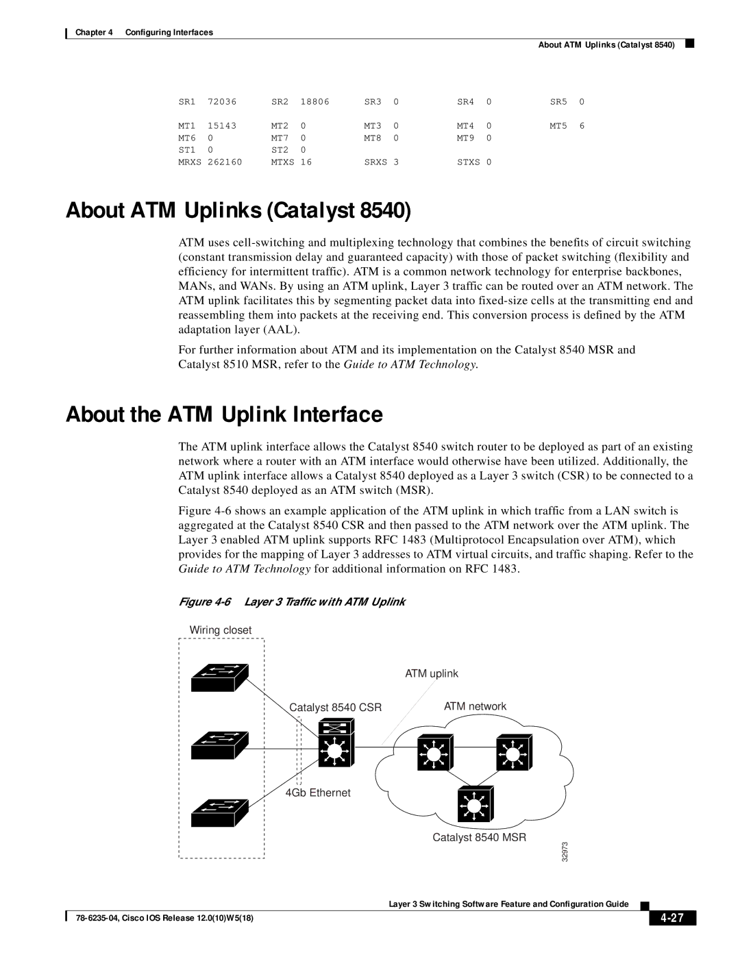
The ATM uplink interface allows the Catalyst 8540 switch router to be deployed as part of an existing network where a router with an ATM interface would otherwise have been utilized. Additionally, the ATM uplink interface allows a Catalyst 8540 deployed as a Layer 3 switch (CSR) to be connected to a Catalyst 8540 deployed as an ATM switch (MSR).
Figure 4-6 shows an example application of the ATM uplink in which traffic from a LAN switch is aggregated at the Catalyst 8540 CSR and then passed to the ATM network over the ATM uplink. The Layer 3 enabled ATM uplink supports RFC 1483 (Multiprotocol Encapsulation over ATM), which provides for the mapping of Layer 3 addresses to ATM virtual circuits, and traffic shaping. Refer to the Guide to ATM Technology for additional information on RFC 1483.
Figure 4-6 Layer 3 Traffic with ATM Uplink
Wiring closet
|
| ATM uplink | |||
Catalyst 8540 CSR |
| ATM network | |||
|
|
|
|
|
|
|
|
|
|
|
|
|
|
|
|
|
|
|
| 4Gb Ethernet |
|
| |||
|
|
| |||||
|
|
|
|
| |||
|
| Catalyst 8540 MSR | |||||
|
| 32973 |
|
|
| ||
|
| Layer 3 Switching Software Feature and Configuration Guide |
|
|
| ||
|
|
| |||||
|
|
|
|
|
| ||
|
|
|
|
|
| ||
