Chapter 4 Configuring Interfaces
Configuring the ATM Uplink Interface (Catalyst 8540)
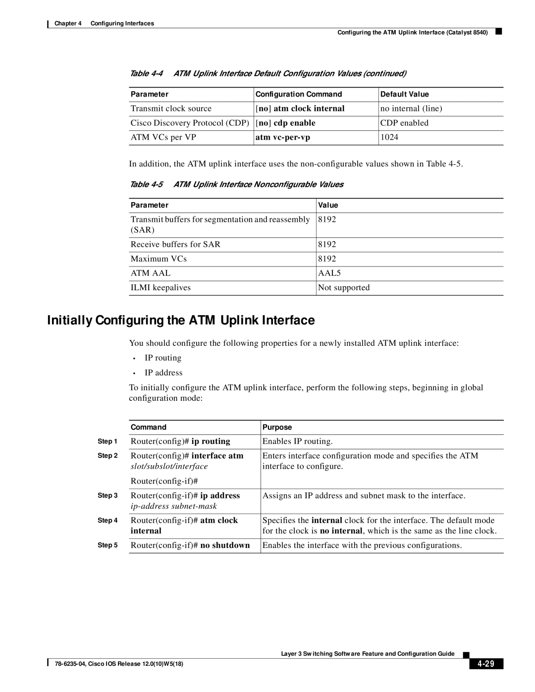
Table
Parameter | Configuration Command | Default Value |
|
|
|
Transmit clock source | [no] atm clock internal | no internal (line) |
|
|
|
Cisco Discovery Protocol (CDP) | [no] cdp enable | CDP enabled |
|
|
|
ATM VCs per VP | atm | 1024 |
|
|
|
In addition, the ATM uplink interface uses the
Table
Parameter | Value |
|
|
Transmit buffers for segmentation and reassembly | 8192 |
(SAR) |
|
|
|
Receive buffers for SAR | 8192 |
|
|
Maximum VCs | 8192 |
|
|
ATM AAL | AAL5 |
|
|
ILMI keepalives | Not supported |
|
|
Initially Configuring the ATM Uplink Interface
You should configure the following properties for a newly installed ATM uplink interface:
•IP routing
•IP address
To initially configure the ATM uplink interface, perform the following steps, beginning in global configuration mode:
| Command | Purpose |
Step 1 |
|
|
Router(config)# ip routing | Enables IP routing. | |
Step 2 |
|
|
Router(config)# interface atm | Enters interface configuration mode and specifies the ATM | |
| slot/subslot/interface | interface to configure. |
|
| |
Step 3 |
|
|
Assigns an IP address and subnet mask to the interface. | ||
|
|
|
Step 4 |
|
|
Specifies the internal clock for the interface. The default mode | ||
| internal | for the clock is no internal, which is the same as the line clock. |
Step 5 |
|
|
Enables the interface with the previous configurations. | ||
|
|
|
|
| Layer 3 Switching Software Feature and Configuration Guide |
|
|
|
|
|
| |||
|
|
|
| ||
|
|
|
|