Chapter 4 Configuring Interfaces
About Layer 3 Switching Interfaces
Step 3 Follow each interface command with the interface configuration commands required for your particular interface.
The commands you enter define the protocols and applications that will run on the interface. The commands are collected and applied to the interface command until you enter another interface command, a command that is not an interface configuration command, or you enter end to return to privileged EXEC mode.
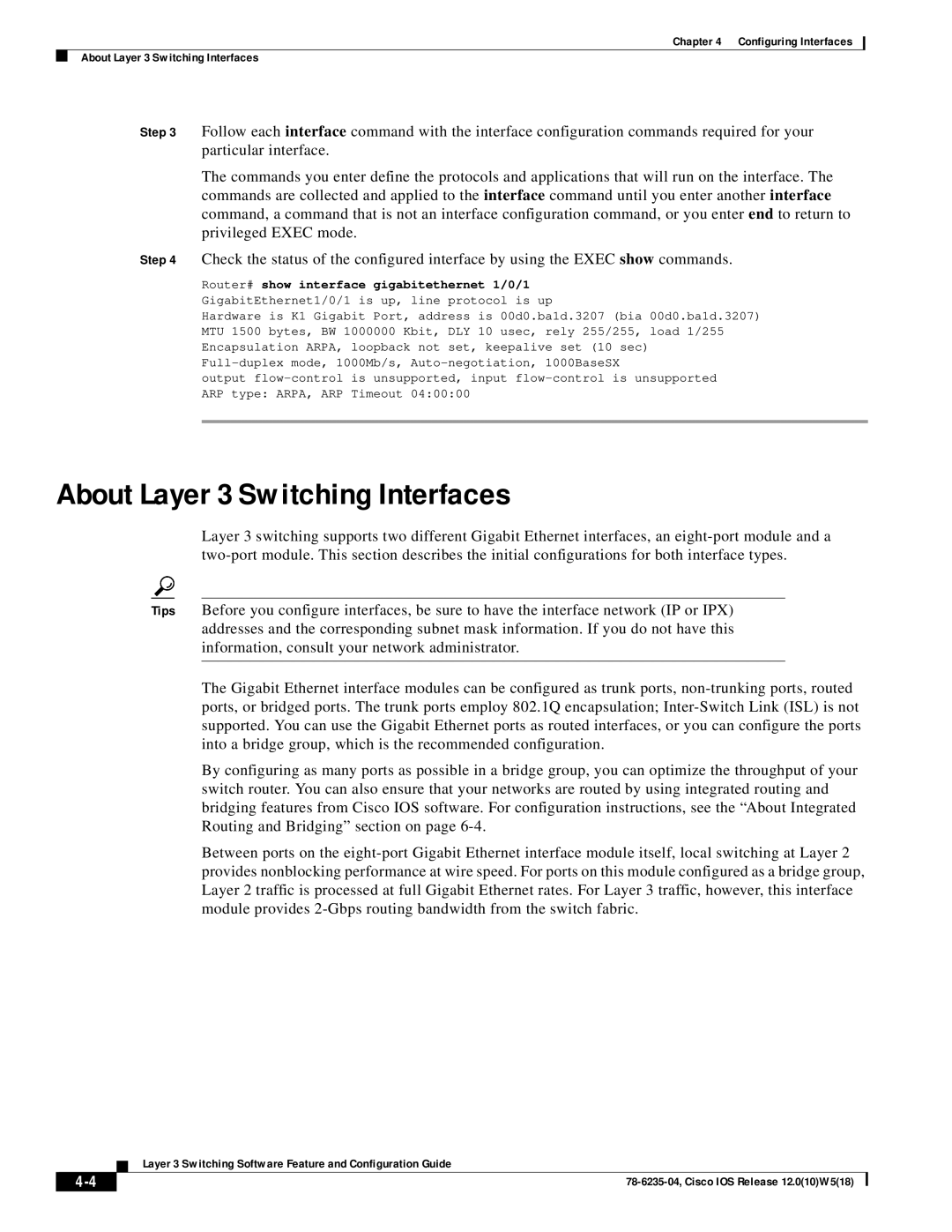
Step 4 Check the status of the configured interface by using the EXEC show commands.
Router# show interface gigabitethernet 1/0/1 GigabitEthernet1/0/1 is up, line protocol is up
Hardware is K1 Gigabit Port, address is 00d0.ba1d.3207 (bia 00d0.ba1d.3207) MTU 1500 bytes, BW 1000000 Kbit, DLY 10 usec, rely 255/255, load 1/255 Encapsulation ARPA, loopback not set, keepalive set (10 sec)
output
About Layer 3 Switching Interfaces
Layer 3 switching supports two different Gigabit Ethernet interfaces, an
Tips Before you configure interfaces, be sure to have the interface network (IP or IPX) addresses and the corresponding subnet mask information. If you do not have this information, consult your network administrator.
The Gigabit Ethernet interface modules can be configured as trunk ports,
By configuring as many ports as possible in a bridge group, you can optimize the throughput of your switch router. You can also ensure that your networks are routed by using integrated routing and bridging features from Cisco IOS software. For configuration instructions, see the “About Integrated Routing and Bridging” section on page
Between ports on the
| Layer 3 Switching Software Feature and Configuration Guide |
