Chapter 4 Configuring Interfaces
Configuring the ATM Uplink Interface (Catalyst 8540)
Configuring SONET Alarms
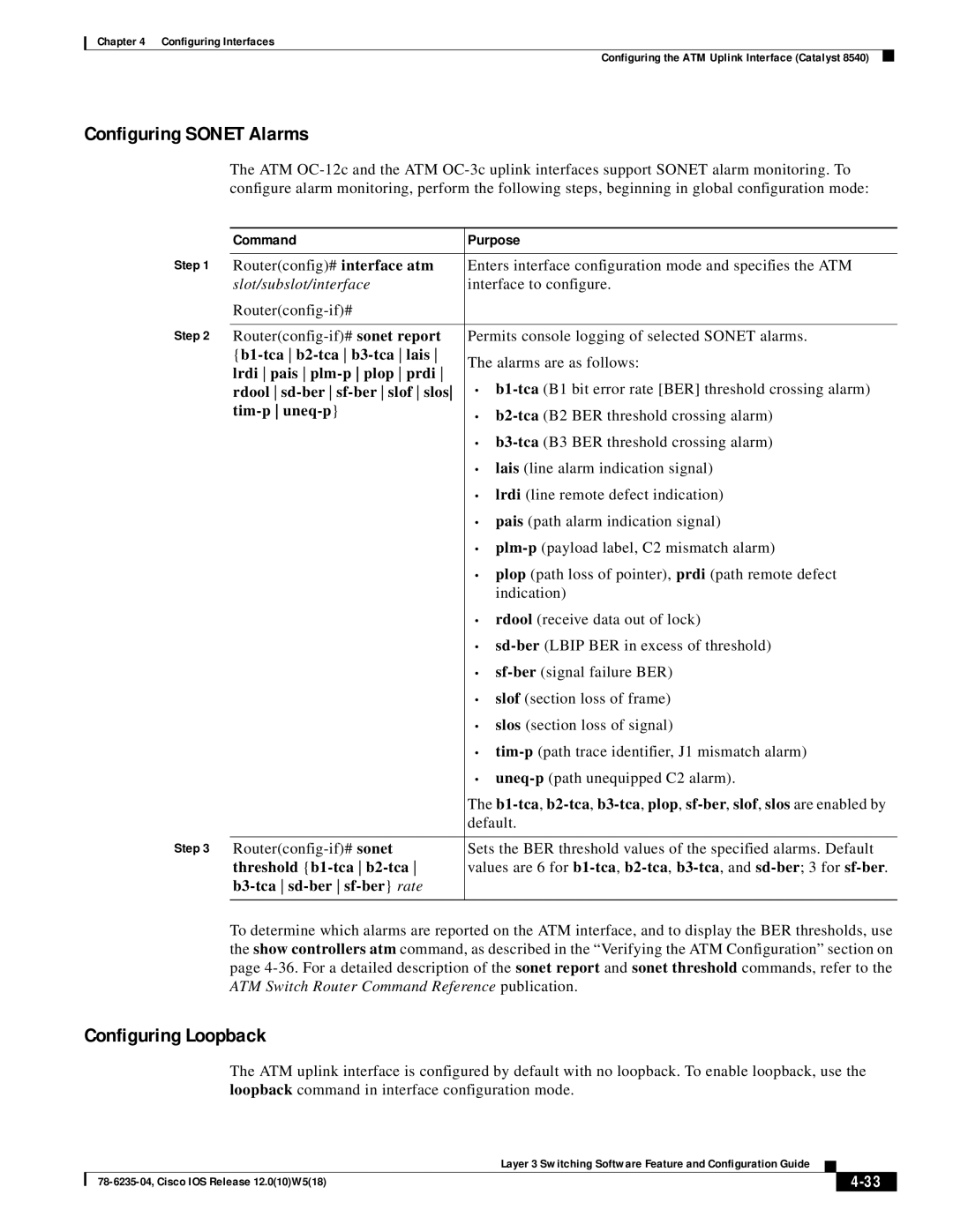
The ATM
| Command | Purpose |
Step 1 |
|
|
Router(config)# interface atm | Enters interface configuration mode and specifies the ATM | |
| slot/subslot/interface | interface to configure. |
|
| |
Step 2 |
|
|
Permits console logging of selected SONET alarms. | ||
| The alarms are as follows: | |
| lrdi pais | |
| • | |
| rdool | |
|
| • |
|
| |
|
| • |
|
| • lais (line alarm indication signal) |
|
| • lrdi (line remote defect indication) |
|
| • pais (path alarm indication signal) |
|
| • |
|
| • plop (path loss of pointer), prdi (path remote defect |
|
| indication) |
|
| • rdool (receive data out of lock) |
|
| • |
|
| • |
|
| • slof (section loss of frame) |
|
| • slos (section loss of signal) |
|
| • |
|
| • |
|
| The |
|
| default. |
Step 3 |
|
|
Sets the BER threshold values of the specified alarms. Default | ||
| threshold | values are 6 for |
|
|
|
|
|
|
To determine which alarms are reported on the ATM interface, and to display the BER thresholds, use the show controllers atm command, as described in the “Verifying the ATM Configuration” section on page
Configuring Loopback
The ATM uplink interface is configured by default with no loopback. To enable loopback, use the loopback command in interface configuration mode.
|
| Layer 3 Switching Software Feature and Configuration Guide |
|
|
|
|
|
| |||
|
|
|
| ||
|
|
|
|
