Chapter 4 Configuring Interfaces
Configuring the POS
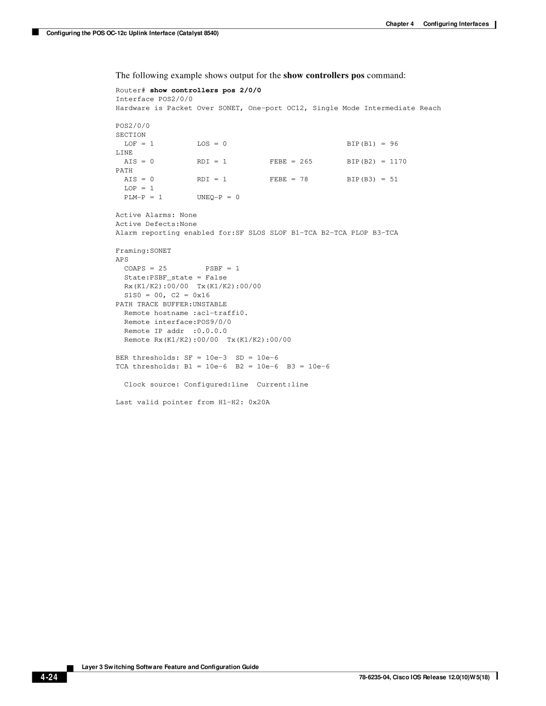
The following example shows output for the show controllers pos command:
Router# show controllers pos 2/0/0
Interface POS2/0/0
Hardware is Packet Over SONET,
POS2/0/0 |
|
|
|
|
SECTION |
|
|
|
|
LOF = | 1 | LOS = 0 |
| BIP(B1) = 96 |
LINE |
|
|
|
|
AIS = | 0 | RDI = 1 | FEBE = 265 | BIP(B2) = 1170 |
PATH |
|
|
|
|
AIS = | 0 | RDI = 1 | FEBE = 78 | BIP(B3) = 51 |
LOP = | 1 |
|
|
|
| = 1 |
|
|
Active Alarms: None
Active Defects:None
Alarm reporting enabled for:SF SLOS SLOF
Framing:SONET |
|
|
APS |
|
|
COAPS = 25 | PSBF = | 1 |
State:PSBF_state | = False |
|
Rx(K1/K2):00/00 | Tx(K1/K2):00/00 | |
S1S0 = 00, C2 = 0x16 |
| |
PATH TRACE BUFFER:UNSTABLE |
| |
Remote | ||
Remote interface:POS9/0/0 |
| |
Remote IP addr | :0.0.0.0 |
|
Remote Rx(K1/K2):00/00 Tx(K1/K2):00/00 | ||
BER thresholds: SF = | SD = | |
TCA thresholds: B1 = | B2 = | |
Clock source: Configured:line Current:line
Last valid pointer from
| Layer 3 Switching Software Feature and Configuration Guide |