Cisco UCS C22 Server Installation and Service Guide
Page
N T E N T S
Special Considerations for Cisco UCS Virtual Interface Cards
Replacing the SuperCap Power Module RAID Backup Unit
Installation for Cisco UCS Integration D-1
Organization
Related Documentation
Audience
Documentation Feedback
Conventions
Säilytä Nämä Ohjeet
Guarde Estas Instruções
GEM Disse Anvisninger
Xii
Obtaining Documentation and Submitting a Service Request
Xiv
A P T E R
Power supply status LED
HDD01 HDD02 HDD03 HDD04
PSU
Acpi
Statement
Installing the Server
Unpacking and Inspecting the Server
Server Documentation Power cord
Installation Guidelines
Preparing for Server Installation
Slide Rail Adjustment Range
Rack Requirements
Equipment Requirements
This section describes how to install the server in a rack
Installing the Server In a Rack
Attaching a Slide-Rail Assembly
Continue with the Initial Server Setup section on
Connecting and Powering On the Server Standalone Mode
Initial Server Setup
Installing the Server Initial Server Setup
OL-26646-01
Cisco UCS C22 Server Installation and Service Guide
NIC Modes and NIC Redundancy Settings
Updating the Bios and Cisco IMC Firmware
System Bios and Cisco IMC Firmware
Accessing the System Bios
Service Headers and Jumpers
Header Location on the Motherboard
This section includes the following topics
Procedure 1 Reboot With recovery.cap File
Using the Bios Recovery Header CN34
Installing the Server Service Headers and Jumpers
Procedure 2 Use Recovery Jumper and recovery.cap File
Installing the Server Service Headers and Jumpers
OL-26646-01
Server Configuration Utility
Server Monitoring and Management Tools
Cisco Integrated Management Interface Cisco IMC
Front Panel LEDs
Status LEDs and Buttons
LED Name State
Rear Panel LEDs and Buttons
Rear Panel LEDs and Buttons
LED Name State
Preparing for Server Component Installation
Shutting Down and Powering Off the Server
Required Equipment
Removing the Top Cover or Front Chassis Panel
Removing and Replacing the Server Top Cover
Removing and Replacing the Front Chassis Panel
Serial Number Location
Replaceable Component Locations
Color-Coded Touch Points
Installing or Replacing Server Components
This section includes the following information
Drive Replacement Procedure
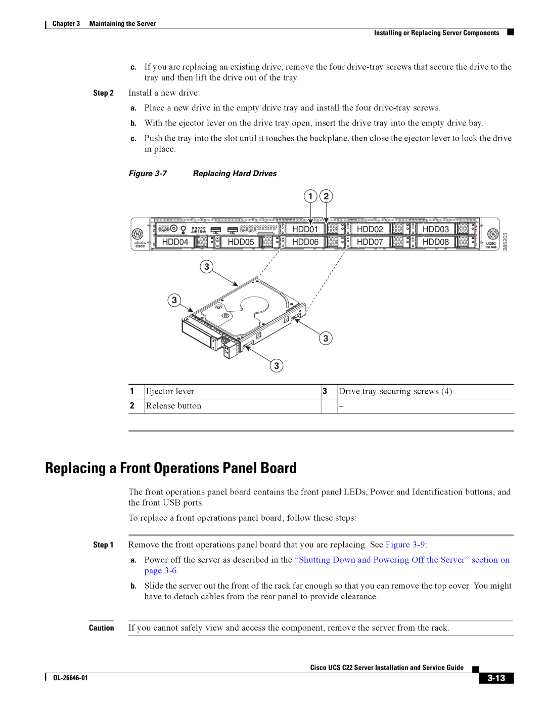
Replacing Hard Drives or Solid State Drives
Drive Population Guidelines
Ejector lever Drive tray securing screws Release button
Replacing a Front Operations Panel Board
OL-26646-01
Replacing the Front Operations Panel Board
Hinged ribbon-cable connectors two Securing screws two
Replacing a Drive Backplane
Replacing the Drive Backplane
FAN SYSFAN2 SYSFAN3 SYSFAN4 SYSFAN5 SYSFAN6
Replacing Fan Modules
SYS FAN23
Replacing DIMMs
Dimm Slot Numbering
Memory Performance Guidelines and Population Rules
Udimm
Dimm Population Rules
A1 B1 D1 E1 A1, B1 A2, B2 D1, E1 D2, E2
Enabling Low-Voltage Dimm Operation
Memory Mirroring
A1 B1 CPU2 slots not available A1, B1 A2, B2
Dimm Replacement Procedure
Software or Firmware Minimum Version
Replacing CPUs and Heatsinks
Single-CPU Restrictions
CPU Replacement Procedure
CPU
Heatsink screws four Hinged CPU cover plate
332668
16 CPU and Pick-and-Place Tool on Pedestal
17 Thermal Grease Application Pattern
Cisco UCS C22 Server Installation and Service Guide
Replacing the Motherboard RTC Battery
Replacing a PCIe Riser
RTC battery holder on motherboard
20 Replacing the PCIe Riser
Chassis alignment points for PCIe riser
PCIe Slots
Replacing a PCIe Card
Replacing a PCIe Card
RAID Controller Card Cable Routing
Resolving Insufficient Memory Space to Execute Option ROMs
Error Code Severity Instance Description
Resolving Insufficient 16-Bit I/O Space
Replacing an Internal USB Flash Drive
Internal USB Flash Drive Replacement Procedure
Cisco USB flash drive socket on motherboard
Enabling or Disabling the Internal USB Port
Replacing the SuperCap Power Module RAID Backup Unit
23 Replacing an Scpm
Scpm bracket
Installing a Trusted Platform Module
24 TPM Socket Location on Motherboard
Set TXT Support to Enabled
25 SCU Upgrade ROM Module Retention Feature
Replacing a SCU Upgrade ROM Module
Replacing a Software RAID Key Module
26 Software RAID Key Module Retention Feature
Power supply handle Power supply release lever
Replacing Power Supplies
Table A-1lists the physical specifications for the server
Physical Specifications
450W Power Supply
Power Specifications
650W Power Supply
Environmental Specifications
OL-26646-01
Supported Power Cords and Plugs
Power Cord, 250 VAC 13 a Nema 6-15 Plug North America
Power Cord, 250 VAC 10 a CEI 23-16 Plug Italy
Power Cord, 250 VAC 10 a MP232 Plug Switzerland
Power Cord, 250 VAC 13 a IEC60320 Plug North America
CAB-9K10A-AU
AC Power Cord Illustrations
CAB-9K10A-EU
CAB-9K10A-SW
CAB-N5K6A-NA
Figure B-13 CAB-C13-CBN, Jumper Power Cord 0.68 m
OL-26646-01
This appendix contains the following sections
RAID Controller Considerations
Supported RAID Controllers and Required Cables
5, 6, 10, 50 Drives 1 mini-SAS 9265CV-8i
Mixing Drive Types in RAID Groups
Best Practices For Mixing Drive Types in RAID Groups
SAS3 Internal LSI MegaRAID PCIe Drives 1 mini-SAS 9220-4i
RAID Controller Migration
SuperCap Power Modules RAID Backup Units
Embedded RAID Controller
Cisco UCS C22 Server Installation and Service Guide
SCU upgrade ROM header Software RAID 5 key header
Enabling the Embedded RAID Controller in the Bios
Disabling the Embedded RAID Controller in the Bios
Launching the LSI Embedded RAID Configuration Utility
Installing LSI MegaSR Drivers For Windows and Linux
Click your model of server in the right-hand column
Microsoft Windows Driver Installation
Windows Server 2008R2 Driver Installation
Downloading the LSI MegaSR Drivers
Updating the Windows Driver
Installing the driver, and then click Properties
Cisco UCS C22 Server Installation and Service Guide
Linux Driver Installation
Preparing Physical Installation Diskettes For Linux
Obtaining the Driver Image File
Preparing Installation Disks With a Linux Operating System
For Rhel 6.x 32- and 64-bit, type
Installing the Red Hat Linux Driver
Installing the Suse Linux Enterprise Server Driver
Press OK
Cable Routing
RAID Controller Cabling
Embedded RAID
Cisco UCS C22 Server Cabling
Backplane and Expander Options
Small Form Factor 8-Drive Backplane Cabling
LSI MegaRAID 9220-8i, 9240-8i, or 9265CV-8i PCIe Card
LSI MegaRAID 9220-4i PCIe Card
Large Form Factor 4-Drive Backplane Cabling
For More Information
Foreign configurations found on adapter
OL-26646-01
OL-26646-01
Installation for Cisco UCS Integration
OL-26646-01