Chapter 2. Hardware Description
3.Rear Port Specification and Connection Examples
Camera Input
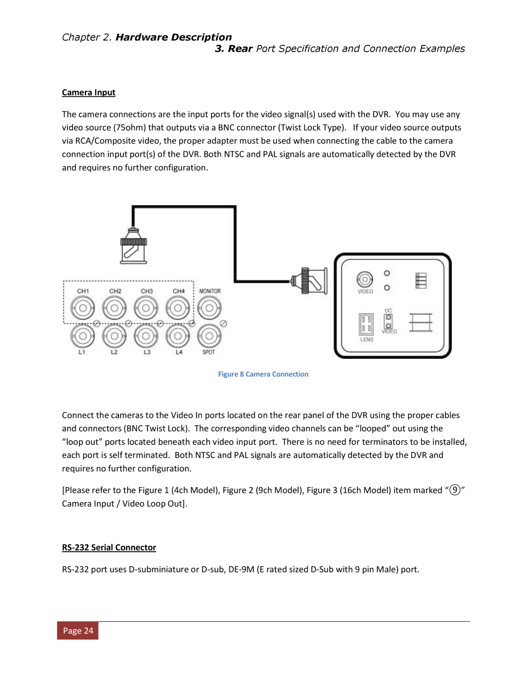
The camera connections are the input ports for the video signal(s) used with the DVR. You may use any video source (75ohm) that outputs via a BNC connector (Twist Lock Type). If your video source outputs via RCA/Composite video, the proper adapter must be used when connecting the cable to the camera connection input port(s) of the DVR. Both NTSC and PAL signals are automatically detected by the DVR and requires no further configuration.
Figure 8 Camera Connection
Connect the cameras to the Video In ports located on the rear panel of the DVR using the proper cables and connectors (BNC Twist Lock). The corresponding video channels can be “looped” out using the “loop out” ports located beneath each video input port. There is no need for terminators to be installed, each port is self terminated. Both NTSC and PAL signals are automatically detected by the DVR and requires no further configuration.
[Please refer to the Figure 1 (4ch Model), Figure 2 (9ch Model), Figure 3 (16ch Model) item marked “⑨” Camera Input / Video Loop Out].
RS-232 Serial Connector
![]() Page 24
Page 24![]()