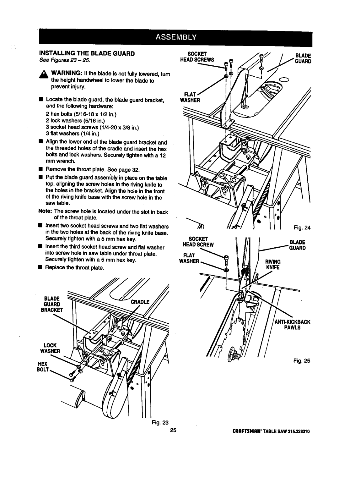
INSTALLING THE BLADE GUARD | SOCKET |
See Figures 23 - 25. | HEADSCREWS |
|
BLADE
WARNING: If the blade is not fully lowered, tum the height handwheel to lower the blade to
prevent injury.
•Locate the blade guard, the blade guard bracket, and the followinghardware:
2 hex bolts
2 lockwashers (5/16 in.)
3 socket head screws
3 fiat washers (1/4 in.)
•Align the lower end of the blade guard bracket and the threaded holes of the cradle and insertthe hex
boltsand _ockwashers. Securely tk3htanwith a 12 mm wrench.
•Remove the throat plate. See page 32.
•Put the blade guard assembly in place on the table top, aligningthe screw holes in the rivingknife to the holes in the bracket. Align the hole in the front of the rivingknife base with the screw hole in the saw table.
Note: The screw hole is located under the slot in back of the throat plate.
•Inserttwo socket head screws and two flat washers in the two holes at the beck of the dying knife base.
Securelytighten with a 5 mm hex key.
•Insertthe third socket head screw and flat washer into screw hole in saw table under throat plate. Securelytighten with a 5 mm hex key.
•Replace the throat plate.
BLADE
GUARD
BRACKET
LOCK
WASHER
FLM
WASHER
SOCKET
HEADSCREW
FLAT
Fig. 24
BLADE
RIVING
KNIFE
PAWLS
Fig. 25
HEX
Fig. 23
25
CRRFTSNnN"TABLESAW315.228310