•Check the 45" setting. Tilt the blade with the bevel handwheel as far as it will go to the left. Place the square against the blade (be sure the square is not against one of the saw teeth). Ifthe blade is not at
45", unscrewthe 45" stop screw (right of blade), turnthe handwheel untilthe blade is correct, and
tighten the screw. Recheck and repeat if neces- sary.
•Check that the scale indicatoris at 45°.
•If not, loosen the scale indicatorwith a screwdriver, adjust it withinthe slot,and retightenthe screw.
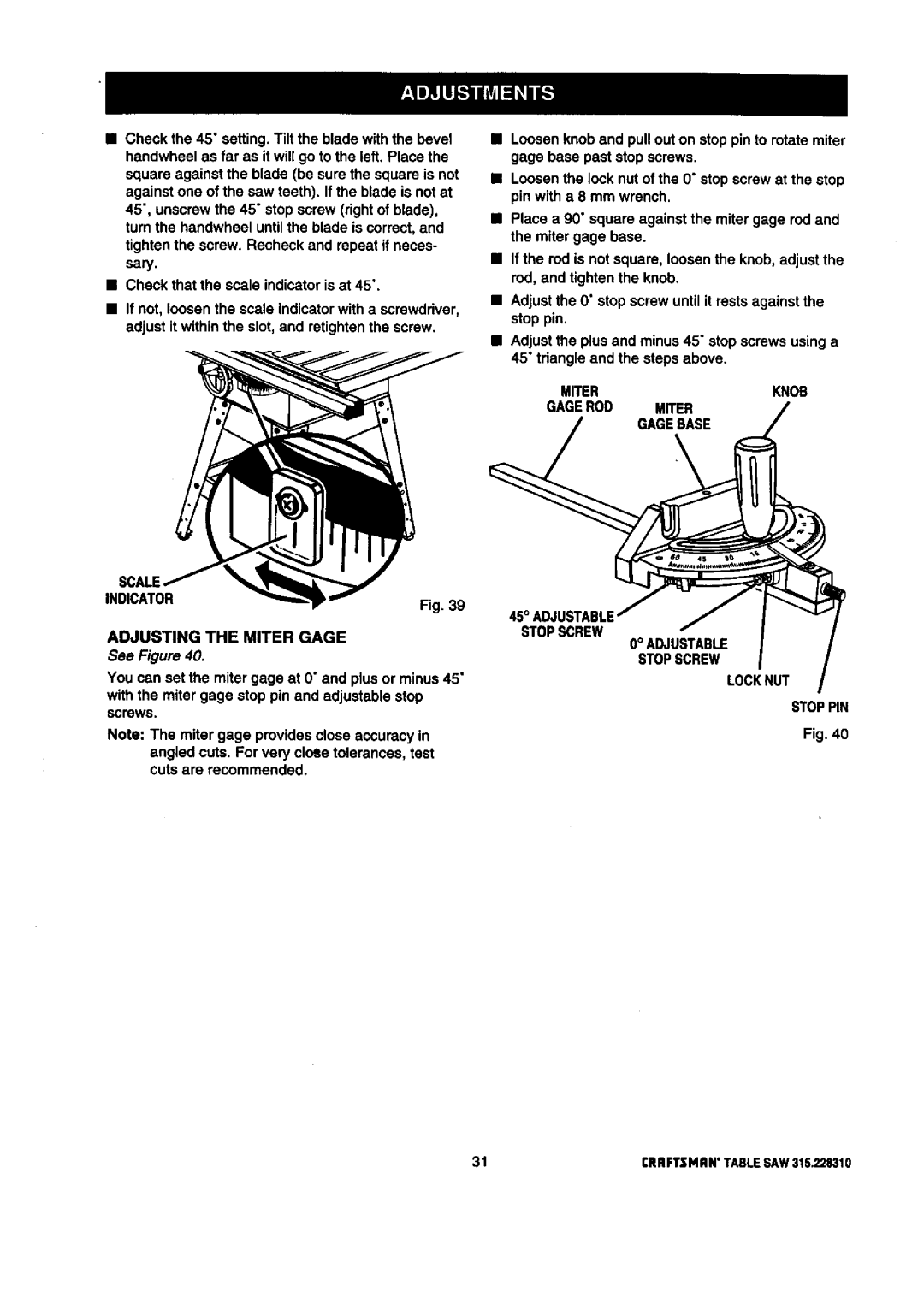
•Loosen knob and pull out on stop pin to rotate miter gage base past stop screws.
•Loosen the lock nut of the 0" stop screw at the stop pin with a 8 mm wrench.
•Place a 90" square against the miter gage rod and the miter gage base.
•If the rod is not square, loosen the knob, adjust the rod, and tighten the knob.
•Adjustthe 0" stop screw until it rests against the stop pin.
•Adjustthe plus and minus45" stop screws using a 45" tdangle and the steps above.
MITERKNOB
GAGEROD MITER
GAGEBASE
SCALE
INDICATOR | Fig. 39 |
|
|
| |
ADJUSTING THE MITER GAGE |
| STOPSCREW |
|
| |
See Figure 40. |
|
|
You can set the miter gage at O"and plus or minus45" |
| |
with the miter gage stop pin and adjustable stop |
| |
screws |
|
|
Note: The miter gage providesclose accuracy in |
| |
angled cuts. For very cloSe tolerances, test |
| |
cuts are recommended. |
|
|
0° ADJUSTABLE STOPSCREW
LOCKNUT
STOPPIN
Fig. 40
31 | rRRFTSMRN" TABLESAW315.228310 |