SL811HS
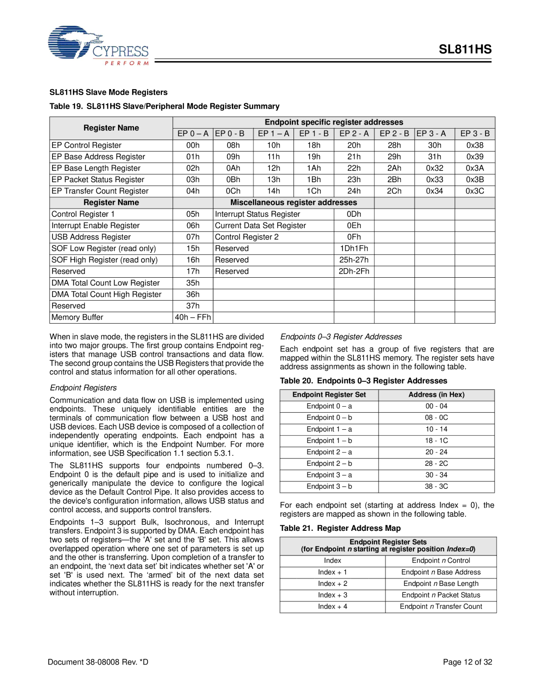
SL811HS Slave Mode Registers
Table 19. SL811HS Slave/Peripheral Mode Register Summary
Register Name |
|
| Endpoint specific register addresses |
|
| |||||
EP 0 – A | EP 0 - B | EP 1 – A | EP 1 - B | EP 2 - A | EP 2 - B | EP 3 - A | EP 3 - B | |||
| ||||||||||
EP Control Register | 00h | 08h | 10h |
| 18h | 20h | 28h | 30h | 0x38 | |
EP Base Address Register | 01h | 09h | 11h |
| 19h | 21h | 29h | 31h | 0x39 | |
EP Base Length Register | 02h | 0Ah | 12h |
| 1Ah | 22h | 2Ah | 0x32 | 0x3A | |
EP Packet Status Register | 03h | 0Bh | 13h |
| 1Bh | 23h | 2Bh | 0x33 | 0x3B | |
EP Transfer Count Register | 04h | 0Ch | 14h |
| 1Ch | 24h | 2Ch | 0x34 | 0x3C | |
Register Name |
| Miscellaneous register addresses |
|
|
| |||||
Control Register 1 | 05h | Interrupt Status Register |
| 0Dh |
|
|
| |||
Interrupt Enable Register | 06h | Current Data Set Register |
| 0Eh |
|
|
| |||
USB Address Register | 07h | Control Register 2 |
| 0Fh |
|
|
| |||
SOF Low Register (read only) | 15h | Reserved |
|
|
| 1Dh1Fh |
|
|
| |
SOF High Register (read only) | 16h | Reserved |
|
|
|
|
|
| ||
Reserved | 17h | Reserved |
|
|
|
|
|
| ||
DMA Total Count Low Register | 35h |
|
|
|
|
|
|
|
| |
DMA Total Count High Register | 36h |
|
|
|
|
|
|
|
| |
Reserved | 37h |
|
|
|
|
|
|
|
| |
Memory Buffer | 40h – FFh |
|
|
|
|
|
|
|
| |
When in slave mode, the registers in the SL811HS are divided into two major groups. The first group contains Endpoint reg- isters that manage USB control transactions and data flow. The second group contains the USB Registers that provide the control and status information for all other operations.
Endpoint Registers
Communication and data flow on USB is implemented using endpoints. These uniquely identifiable entities are the terminals of communication flow between a USB host and USB devices. Each USB device is composed of a collection of independently operating endpoints. Each endpoint has a unique identifier, which is the Endpoint Number. For more information, see USB Specification 1.1 section 5.3.1.
The SL811HS supports four endpoints numbered
Endpoints
Endpoints 0–3 Register Addresses
Each endpoint set has a group of five registers that are mapped within the SL811HS memory. The register sets have address assignments as shown in the following table.
Table 20. Endpoints 0–3 Register Addresses
Endpoint Register Set | Address (in Hex) |
Endpoint 0 – a | 00 - 04 |
|
|
Endpoint 0 – b | 08 - 0C |
|
|
Endpoint 1 – a | 10 - 14 |
|
|
Endpoint 1 – b | 18 - 1C |
|
|
Endpoint 2 – a | 20 - 24 |
|
|
Endpoint 2 – b | 28 - 2C |
|
|
Endpoint 3 – a | 30 - 34 |
|
|
Endpoint 3 – b | 38 - 3C |
|
|
For each endpoint set (starting at address Index = 0), the registers are mapped as shown in the following table.
Table 21. Register Address Map
Endpoint Register Sets
(for Endpoint n starting at register position Index=0)
Index | Endpoint n Control |
|
|
Index + 1 | Endpoint n Base Address |
|
|
Index + 2 | Endpoint n Base Length |
|
|
Index + 3 | Endpoint n Packet Status |
|
|
Index + 4 | Endpoint n Transfer Count |
|
|
Document | Page 12 of 32 |